Day 273: DI..why?! – How to install a smart light switch

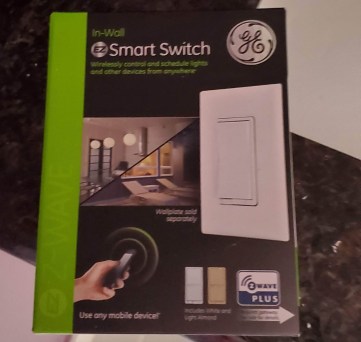
Today we are installing a pair of these, we’ll cover how to install one and you’ll be able to do as many as you want once you get the first one down!
I had three options for a post today, so we’re going to go with the simplest and probably most helpful. Here’s the scenario, you want to change out a light switch, but you don’t know how to do it. You could pay someone, but why spend the money? You’re in luck, this is a simple job and I think anyone can do it, why did I change out a light switch, well I’ll tell you my reasons, but they may not be the same as yours, that’s fine too. No judgement here!
Part of my quest to making my home more accessible involves the simple light switch. I’m changing them out for some GE z-wave light “smart” switches. It’s a really simple task and on a scale of 1 to 10, 10 being the most difficult thing I could think of in a DIY situation, I would put this at a 1, it’s about as simple as it gets and it is very hard to screw up. I like being able to control them because I can set timers and things for them so they don’t stay on for very long if I forget to turn them off (stupid brain!).
Why z-wave? Well in smart home terms, z-wave is a very common internet of things (IoT) communication standard. More importantly it is one that does not use WiFi, so it doesn’t clog up your bandwidth. This is great for several reasons, but the biggest is that I am not tied to a single company. I can comfortably say that I will be able to find the hardware to control these switches even if a particular smart hub company goes out of business (like wink is about to do, no seriously if you use wink I would find a different option like today). My advice, don’t buy the branded communication standards for that reason.
So with that let’s look at how this is done. First things first… and I do not have a picture of this because it is very specific to your case. You need to shut the power off to the switch. To do this turn the light/fan/whatever on and flip the breaker switch you think controls this circuit, if the device is no longer on/powered/whatever then you found the right one, if not keep going until you find it. With the power off you can safely work with the switch! I did an extensive job documenting this since I promised to be better about it so let’s start from the beginning.
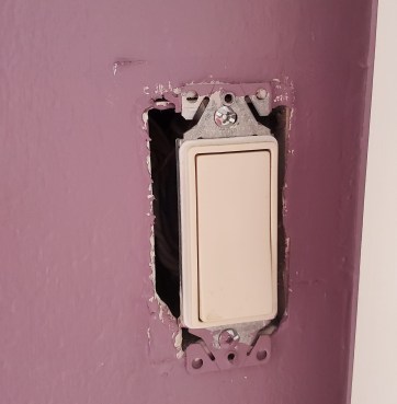
First you need to remove the switch plate, it’s the two screws that are (most likely) visible. They make pop on plates that hide the screws, I think they are ugly, but if you have this style then it literally pulls off and the screws are underneath. Remove them and you should have something that looks like this (mine is a rocker switch you may have a different style, but it’s all the same thing in the end I promise).
The previous screws were probably flat head screws (a single slot) the screws that hold this into the wall are going to be phillips screws (a x slot), that’s just the convention, don’t ask me. Go ahead and pull those two screws and the switch will now pull away from the wall. There will be some resistance here. There are wires attached to it, but fear not! It should pull away without having to yank too hard. So what do all those wires do? Let’s run through it. (I told you I documented this well!)
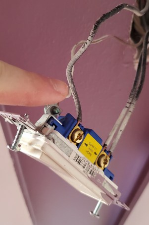
Depending on your set up you will have at LEAST 3 wires, I had 4, I’ll explain later in the post what that means. This wire (the one I am pointing to) is our load. When we say load we just mean whatever device this controls, so in my case a light bulb, but you may have a fan or something else the switch controls, that would be your load. Note: the documentation for the light switch will use the term load. It is good to be familiar with what they mean by that.
In action movies they always tell you to cut the red wire, you may have noticed all my wires are black (with some white spray paint, but they are all black). How do I know that is my load wire? I could use a multimeter to check (I advise you get one for any electrical project), but I already have the power off so it wouldn’t do me any good. In this case you can observe a few things, the first is that it is the top wire, a switch is one way, so chances are your top wire will be your load wire.
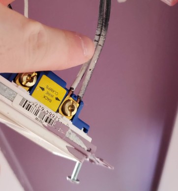
The second are these wires (the pair I am pointing to in the photo above). I know (because I shut the power off to the circuit) that there are several things that are powered on this circuit because they are off too, so I expected to find multiple wires here. You may find the same thing and there is a good chance this is called your line wire. Your line wire(s) are the wires that carry the electricity. If I were to disconnect that single load wire from the image above this and turn the power back on, it would be cold (as in no power), where as my line wires would then be hot (meaning there is electricity flowing through them). I could turn the power on and very carefully use a multimeter to confirm these are my line wires, but I had experience with how my house was wired, so I was confident this was the case. Next we see this wire:
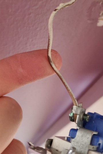
It’s hard to tell because it is covered in white spray paint, but this is a bare copper wire. It may seem scary to find a bare wire in your wall, but this is our ground wire. A ground provides a way to complete the circuit and prevents shorting in emergencies. The ground wire will always be a bare, so it’s easy to tell it apart from the others. This one was attached to the top of the switch as you can see and folded over. Instead of trying to unscrew this wire, I just cut it. It’s easier and copper gets brittle over time. There was a good chance if I tried to bend that piece back it would’ve broke anyway, so why not get a fresh part?
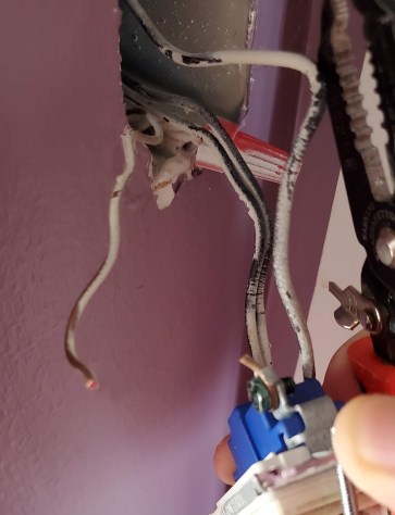
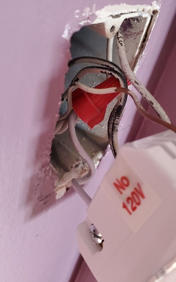
See, documented everything nicely this time. I had a set of wire strippers (seen in the photo) that I used to cut it. Now we need to talk about the neutral wire. In newer construction (I think it’s like 2000 or newer, but don’t quote me on that) houses are required to have a neutral wire, neutral does not mean ground! It has a slight voltage about 2 volts or so (probably less) and completes the circuit for the line wire. In z-wave switches like the one I am putting in, we need this to supply power to it. You can read more about the function of a neutral wire here, but all you really need to know is that it isn’t the same thing as your ground. This wire will always be white and even though the old switch doesn’t use it, there should be several of these white wires in the electrical box all tied together (see the image below where I am pointing to it).

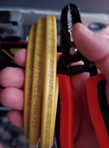
Notice it’s capped off, that unscrews by hand and should be easily removable if you unscrew it. Note: trying to pull it will damage it, so just unscrew it and it will literally fall right off. That will expose the bare wires, now I always have some extra romex cable (the cable that runs behind your walls) handy to attach a single wire from this to my switch, however the kit comes with the wire as well. For completeness, here’s a shot of my romex cable, it never hurts to be prepared if you’re doing electrical work, but for this install it was not needed.
So at this point you should still have a few wires attached to the switch. You can use the screws on the side of the switch where they attach to unscrew them and the wires should come off easily, the ends won’t typically be bent like this ground wire is. You’ll want to bend them in such a way that you can tell the load from the line wires. I bend my load wire up because that is how it attaches to my switch and the line wires down. You’ll notice my short added white neutral wire as well. The neutral and the ground wires can be bent however you want since they are easy to tell apart. You should either label your black lines or bend them like I have to tell them apart or you’ll end up messing up the rest of the install.
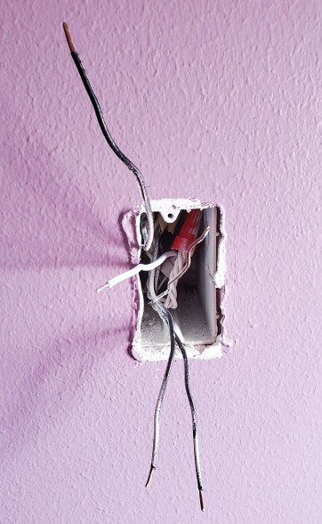
This shot reminds me of a horror movie for some reason.
So let’s take a look at my replacement switches, I had two I was installing here, but we only need to cover one since it’s the same process for the other.
It’s fairly straightforward to unpack these, so I don’t have photos of that. Here is what the back of the switch looks like and you can see why I used the terminology I did, because the switch is labeled load (bottom left), line (bottom right), neutral (top right) and ground (center left).
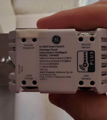
You may also notice there is a traveler label (top left), that is for a 3-way (or more) switch setup and to use it you just take off the piece of tape reminding you not to connect power here. A 3-way circuit has 2 switches controlling the light, a 4-way has 3 switches… you get the idea and yeah the numbering is confusing, but for this install we had 1 switch controlling 1 light so we didn’t need the traveler wire. I may cover that if I do any more 3 (or more) way switches, but that probably won’t happen since most of my switches are already swapped and I don’t think I have a 3-way circuit left to do. So that said, let’s wire everything in! Same procedure, there is a screw terminal on each side and those holes are for the wires so we just put the wires into the hole, screw down the terminal and give it a little tug to make sure it is tight and attached properly. First up the line wires, remember these are our wires that carry electricity so it’s important to make sure they are attached, sometimes you may not screw them down tight enough or it may slip out, so give it a little tug once it is tight to make sure it is secure.

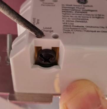
I like this photo since it shows the screw terminal very nicely, it’s really easy to just plug them into the slots and screw it down. You may need to strip the wire back a little (to expose the copper), but I did not need to do that and chances are, unless the wire broke when you removed it, you won’t need to do that either. Now we can attach the load wire. Remember to keep these separate so you know which is which. You can also attach a piece of masking tape and label them if you are worried, but if you bend them like I did you should be good.
Now that we got the hang of it, go ahead and attach the ground and neutral wires to their correct places and you should have something that looks like this.
This shot shows the wire I added to the neutral bundle, I didn’t take any photos showing that step because it’s hard to explain even with photos. You just twist the new wire around the bare wires (they will be tightly twisted together once you remove the cap) then screw the cap back on until it tightens down. If it doesn’t tighten down the first time you may need to readjust the wire you just added a little and keep trying, it will tighten down eventually I promise. Now for the hard part. If you noticed the new switch is quite a bit larger than the old one, so we need to cram it all back into the box. To do this I push it in as far as it will go and just start the top and bottom screws slightly. Once they catch and I am sure I’m not going to pinch any wires, I screw them down and use the switch to compress the wires into the box for me.
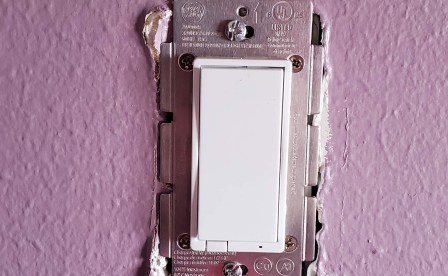
You’ll notice that it is again the phillips head screws. It’s the convention, so we go with it. Now that this is all screwed down you have two options, turn the power back on and make sure everything works or you can put the faceplate back on and that is just one more step if you missed something or if the wire wasn’t attached correctly… you did give it a little tug, right? Since I’ve done so very many of these, I decide to roll the dice and attach the faceplate. Flip the breaker back on and that SHOULD be all there is to this little project.
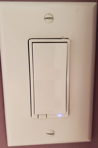
When you go back with the power on, you should be greeted with this little blue light (for the GE switches anyway, some others have different colors). This is a good sign and typically means everything is connected properly. Flip the newly installed switch and see what happens. If the light/fan/whatever came on then you did it! If it doesn’t or the light is not on then chances are one of your cables are loose! Turn the power off and pull the switch, it should be obvious what the problem is. If it isn’t, now would be a good time to turn the power back on and very carefully use a multimeter to make sure your load and line wires are correct.
This took me about 10 minutes for both once I got the power off and my tools together. That’s all there is to it! Pat yourself on the back and next time we can take a look at what I’m calling the forever cabinet removal. You’ll see what I mean tomorrow.
One small note, these smart switches are made specifically for lights, they sell switches that are used to control fans separately. You never want to use a light switch for a fan because the amount of current they pull is higher than what the switch can safely provide. This means it will eventually burn out the switch (you don’t want that)! You can do the reverse and use a fan switch for a light and nothing bad will happen, but since the fan switches typically cost ~$20 more you probably don’t want to do that either. They are clearly labeled on the switch itself what they are for, the fan switch will say directly on the switch that it is designed for a fan.


But enough about us, what about you?