Day 306: Solid Modeling – Week 2
We’re back again with week 2 of solid modeling for beginners! For those of you just joining in, you can read the introduction (pre-week 1) in this post. You can also find all the posts in this series (including week 1) in the Solid modeling for beginners category. Solid modeling isn’t too difficult, but it does take time and it does mean you need to learn to think about objects in different ways. Week 1 did a great job of introducing this type of thought process and today we’re going to continue from where that left off. Let’s just dive right in!
Last week I modeled a seemingly very complex cat toy. I showed you that we could break complex objects into simple shapes and use those simple shapes to recreate the object. Now, you could do this with just about anything (the exception being forks, trust me they are not easy to model funny enough).
I did this step by step, but I could do the entire thing in one shot. I chose not to do this for a reason.. Today we aren’t going to dive into how to use the software quite yet, instead we are going to look at another reason why planning is important. I know that doesn’t sound as exciting, but learning this is harder than learning the software and it’s far more useful.
All the solid modeling software out there does basically the same things, some better than others, but you have the same tools. So once you learn how to do it in one software, making the jump to another isn’t too difficult. Learning how to plan your solid model and how to look at objects is a skill that will follow you and one that isn’t as intuitive as some of the software you’ll use. Don’t worry next week we’ll get into the software itself, but today let’s go through how to create the same cat toy, but in one step. Then I’ll explain to you why that is a bad idea.
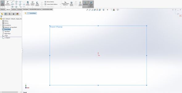
Our old friend, the front plane
Okay since this is one step, I’m going to break it down and show you what I’m doing. I’m not going to tell you why this is a bad idea, maybe you’ll figure it out, maybe you won’t, but it’s okay you’re learning so no judgement here. Okay, so as with above, we enter the front plan by creating a sketch (notice I’m in the sketch now). As with last post, we’ll create the chopped cone that we had before. Notice I’m using the exact measurements we took in that last post for this one.
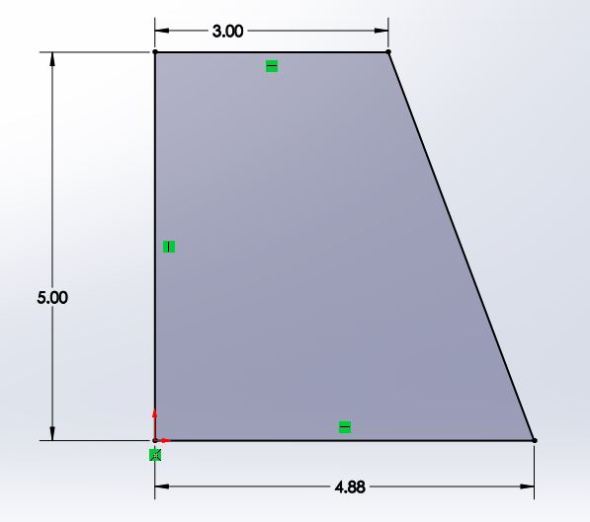
Close up of our newly created sketch just like in our last post.
This is where we take a hard left from the last post though. Last time we revolved this sketch to create our shape. We’re not doing that we’re going all out and creating this in one shot. So to do that, we need to add some circles using the circle tool, shown highlighted in the image below.

Don’t worry if you’re not going to be using solidworks for this class, we’ll go into how to do all this with the free software sketchup, but the tools are very similar so I want to highlight them here a little. Plus, I am teaching a class using solidworks so this will help them. Speaking of which, hi!
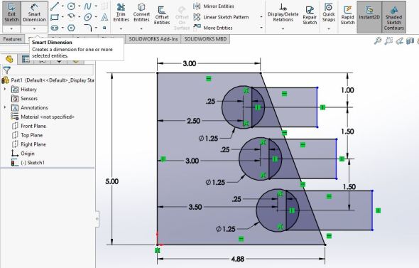
Now I draw my circles and dimension everything using smart dimension. To use smart dimension I click the tool, highlighted in the image below, then click on the line I want to use to offset the circle I made. In this case I’m using the 5 inch line in the center of the cat toy to offset my circles. Notice I organized my dimensions so you can easily read them. This is important because you want to be able to quickly get whatever dimensions you need. If you overlap them or they are hard to read and you are using this part for something other than for fun, you run the risk of messing something up. In this case, I organized them so you could read them easily. In short, please be mindful of how you dimension your part. You can drag your dimensions by left clicking and holding, then dragging it to a place that makes the most sense.
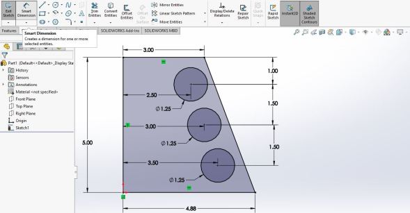
Notice all my lines are black. This means they are fully defined by the dimensions I gave. In other words there is only one solution using the measurements I defined so all my lines are now fixed in place. If I change one of those dimensions, my part will move in very predictable ways every time. You don’t need to fully define your lines, but it helps in some cases.
Okay, now we have our lines so let’s add our rectangles like we did in the previous post. To do that we’ll click the rectangle tool, highlighted in the image below and draw three rectangles.

There are several different ways to define a rectangle. For this case we’re using the corner rectangle, which is the default type, but you can use whatever you want. The same thing applies to the circle tool, you have several different ways to define the circle.
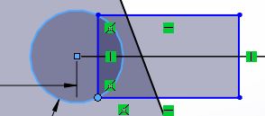
Now that I’ve drawn my rectangles, I need to make the corners that are near the circles touch the circles themselves. This is called making them coincident. The coincident relation means that whatever you set will be touching each other. See the image below.

A coincident relation means that no matter how solidworks solves for the part, it has to be touching. This fixes that corner of the rectangle to the circle such that if I drag the rectangle anywhere, that corner will stay attached to the circle.
In this case I want the corner of my rectangle to touch the circle so I click on the corner, hold shift, click on the circle and click the corner of the rectangle — NOT THE LINES — you want the corner coincident, if you click a line it will make that line coincident and this next step will not do much. The image below shows the coincident option, red circle to the left of the image, and the two things that I am making coincident, the red circle to the right of the image.

By selecting the corner and the circle (red circle to the right) the properties window appears to the left. From there I can select coincident relation (red circle to the left).
Once I do that, a new icon appears by the corner of the rectangle signifying that there is a relation attached to it as shown in the image below. We repeat this step for the remaining rectangles.
Once I have my coincident relation set for all the corners of the rectangles I can offset them a fixed distance from the center of the circle. This will make each of them uniform when I go on to the next steps. I used the smart dimension tool to offset the end of the rectangle to the center of the circle by 0.25 inches. Since I’m freehanding all this again it was an aesthetics thing and not because I measured from the cat toy. I could take measurements, but this is an example part, so there is no need. Notice I made my dimensions easy to read again, but it’s getting really crowded. This is just part of the issue with doing everything in one sketch and it’s only going to get worse as we continue.
As with before, the distance our rectangles stick out don’t matter so the far right lines are still blue because I never defined a width. Everything else is defined nicely so it’s all black.
Now we can use the trim entities tool to create the basic shape of our cat toy. The tool I’m using is shown highlighted (pop out explainer window) below.
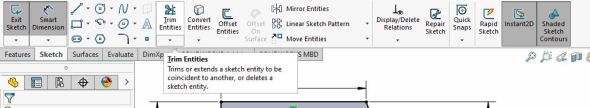
This tool will cut any line up to the next line, you’ll see why that is useful in a moment, but this tool is one of my bread and butter tools. It gets used A LOT in the things I make.
Click and hold next to the line you want to cut, it works like scissors (just like the icon for it). Click, hold, and drag across whatever lines you want to cut. It will create a grey line as you drag and anything that grey line touches gets cut back to the intersection of another line. The image below shows this process in action (see the grey line).
The trim entities tool removes lines up to the first intersection. This lets us create weird shapes (like a cat toy) without having to hand draw all the intricate shapes.
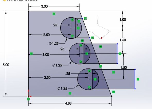
So we do this for all the parts until we have the cat toy shape we want. Below is an image showing what the end result was from the trim entities tool. Note, just like all the tools, the trim entities tool has other options for how it cuts, but I rarely use any other option besides the default (see the options menu to the left of the image below).
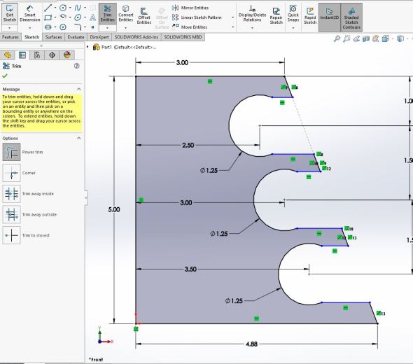
Okay, getting close to being done now. We have our cat toy fairly cut out, but there are still a few things left to do. Notice I’m still in the trim entities tool, you can see the menu to the left that gives you different options for how the tool works, but I only really use the default option.
So next I’m going to set the 5 inch line as a line for construction. You’ll see why in a few steps. To do that, I just click the line and select the for construction option. This means solidworks will not treat it as a line that I’m using to create my shape. It also means that grey infill to our shape is gone because it is no longer a closed shape.

By clicking the line the menu to the left appears and I selected for construction (circled in red). This also highlights an interesting aspect of solidworks. The part is no longer closed (it does not have a boundary, so it is no longer filled in with that grey you see in some of the other images. This is a useful way to double check that your sketches are closed (if you want them to be closed that is).
So now we are going to add the hole to the inside of the part, the one we cut extruded then drafted to fit inside the shape. To do this step I’m just clicking the line tool and freehanding the line where I think it should be. Because it is a cat toy and the company would like to save material where possible we’re going to put this very close to the circles we cut. Again, I’m doing this without measurements so it’s a purely style choice. I then use the trim entities tool to cut the overhanging line back to the line I just drew. I didn’t show this step because we already covered something similar above and the post is getting long again.


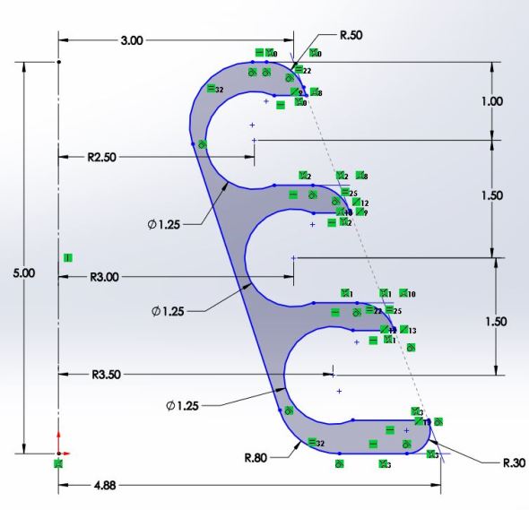
Okay time to finish this part off. Now what I want to do is add the fillets. I meant it when I said we were going to do this all in one sketch, this is how. So I’ll use my fillet tool (shown below) to add the rounded edges of the toy to the sketch now before we finish the part. For the outer edges, I’m thinking a radius of 0.5 will do. The bottom and the inside hole (that line we just drew) will have to be a different radius, but let’s add that to the few we can do. The image below shows me selecting the corner dot of each of the edges I want to add the fillet to. The 0.5 inches is set by the fillet parameters shown in the left menu in the image below. I add a 0.3 radius fillet to the bottom edge and a 0.8 fillet to the inside hole (the line we just added above). The result of which is shown below as well.


Before we continue I’ll highlight one of the issues already and explain in detail once we finish the part. Notice how when we started all the lines were black and fully defined. Now all our lines are blue, meaning none of them are fully defined with the exception of the line we are using for construction to the left. This is a big issue and I’ll touch on why in just a moment.
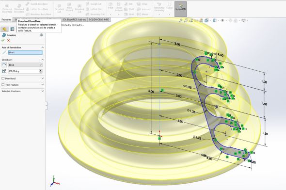
So to finish our part, we will revolve around the line we just set for construction. To do that, I stay in my sketch, but I click the features tab next to the sketch tab. Next, I click the revolved boss/base function and select the line for construction as my axis of revolution. Before I close the revolve I’ve taken a screenshot to show you what you would see if you have access to solidworks and are following along.
Our cat toy looks very much like a cat toy now. Notice the axis of revolution is set as the line we marked as for construction at the beginning of the tutorial (blue dashed line in the center of the cat toy, hard to see I know).
Once I accept the revolve I get the final part. Just for fun I added a touch of color. I won’t cover how I did that today, but it’s a nice way to make a part look more finished.
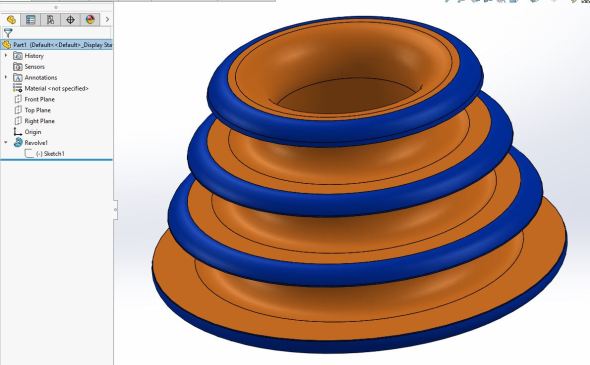
Arguably it looks closer to the real thing than the last one because I set the rectangle offset to be smaller than the last one.
Notice the feature tree to the left. I have a single sketch and a single revolve. We did this entire thing in one shot. Never do this. Besides the fact that none of my lines are fully defined there is another issue at play here.
Say I want to 3D print this toy for my cat, but I realize after doing it I really wanted a larger or smaller toy than what I got. Well how would I easily edit this mess of a sketch to do that? What if after printing it the balls come out because I set the offset that keeps them in place too small? How would I do that in the sketch I just created?
Yes, it can be done, but is it easy? No, it certainly is not. This is why it helps to break your steps up. It doesn’t mean you can’t do the entire thing in one shot, it just isn’t a good practice. More importantly if you scroll through what we just did, we lost a LOT of dimensions of the base lines. Without that information, editing this single sketch would be awfully difficult.
Notice that the lines that make up the outside of the cat toy have very little if any dimensions. Nothing is defined fully anymore!
So with that next week I think we are safe to dive into using the software sketchup from here forward. I may bounce between the two softwares, but I’ll try to make sure I cover everything we do in sketchup as well. Now, I’ll be using the downloaded version so I’ll get 30 days free which will give me access to the tools I need to teach you some of the things you can do with the software. The free version is fully online and is still extremely powerful so feel free to follow along with that, but there are limitations. If you’re following this as I’m posting them and want to activate your 30 day trial, I would wait until I post next week’s topic before you do so you can get the most out of the free trial.
TL;DR for the last two weeks: Don’t make everything in one sketch, it’s hard to work with if you do. Think about how to break your complex part into simple shapes before you start trying to make it, it will save you a lot of time, effort, and headaches.
See you all next week!


But enough about us, what about you?