Day 299: Solid Modeling – Week 1
Welcome to solid modeling for beginners! Each week I’ll post some new and exciting things so you can try your hand at solid modeling. It’s easier than it looks to get started and once you do, you’ll be able to create amazing things that you can 3D print, plans to build something really cool, or maybe you just want to create some art! You can do anything you want with solid modeling, that’s the beauty of it! Let’s get started.
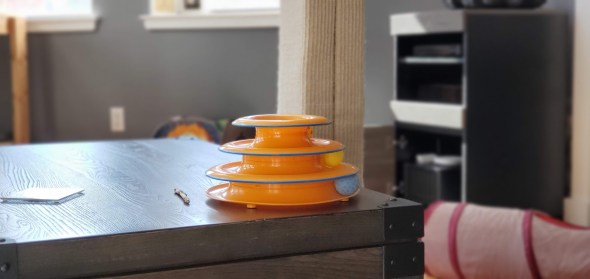
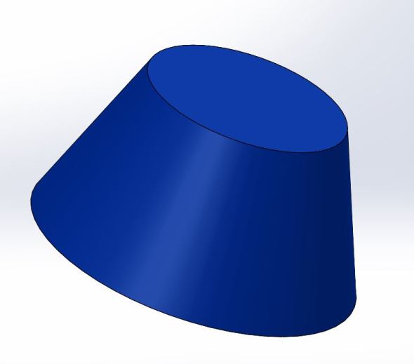
So this week is more show and tell. Before we can start solid modeling you need to learn to see objects as simple shapes. Now, personally I think the best way to explain this is to show you how to do this firsthand. So today I will be using solidworks to recreate this cat toy, shown below!
It just happened to be the most complex looking shape I could find, but when we get started you’ll see that in reality, it’s just a few really basic shapes that you combine to get this design. Now I’m going to break these steps down as a demonstration, but there is an even simpler way to do it by combining all the steps. Basically we are going the long way so you can understand how to start looking at things you want to solid model, but it isn’t the fastest or easiest way. It’s just the best way to get you thinking about solid modeling.
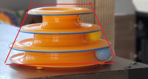
With that said, I had someone in my class cheat (Hey K, you big cheater lol!) and she tried to hand draw the outer shape and revolve it around an axis. If that doesn’t mean anything to you, don’t worry I’ll explain. However, we’re going to do it the way I showed my class. First if we stare at this shape long enough the first thing that jumps out at me is that it’s really just a cone with the top cut off, like outlined below.
So that’s the shape we will use to create our model with! Now I’m going to demo this in solidworks, it’s my prefered solid modeling software, but you can use sketchup to do the same. I’m going to activate a free 30 day trial in about 2 weeks so you’ll be able to follow along more closely at home using that and I’ll make sure to show you how you can do this in sketchup as well. However, for these first few classes, I really want you to think about HOW shapes make up the object. By understanding that, we can create almost anything and you’ll make it look easy!
After taking three rough measurements of my cat toy, I drew this same basic shape (seen above) on the front plane in solidworks by going to the sketch menu in solidworks and clicking sketch and selecting the front plane. Next I used the line tool and drew the basic shape, then I used the smart dimension tool to dimension the shape. The measurements were 1/2 the base, 1/2 the top, and the height. Now I’m only drawing half of this because we are going to revolve the shape about the center axis, again if you are confused, we will see it in just a moment. Below is the shape I drew with the measurements I found.
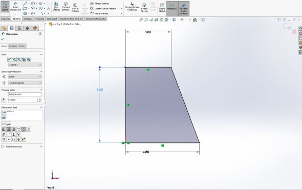
Our basic shape of the cat toy, or at least half of it. Because our toy is circular, we only need half. You’ll see why in the next step!
Now keep this in mind, I’m going to freehand a lot of this. However, getting the rough measurements for the shape means it will look more like the cat toy when I’m done than if I just freehanded all of it. By freehand I mean guessing the measurements of the rest of the changes we will be making to the model. This is just a demo so the measurements in this example don’t matter. If I were making something to 3D print, or a blueprint for something I was going to build, then I would definitely want measurements, keep that in mind because when you model something the scale can be way off if you do not use measurements for the things you make, which I will be showing in the next class.
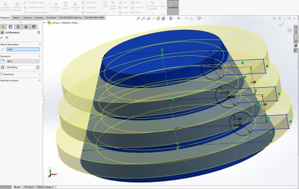
Now we have our basic shape and it looks like 1/2 a cat toy… if we squint hard enough. Next, I’m going to use the revolved boss/base command in the features menu in the features menu. Below you can see what that looks like. The axis of revolution is labeled as line 1. Line 1 is the blue highlighted line and was the left straight line in the drawing I made above. With that line as our axis of revolution we now create a circular shape that is the correct width at the base and top as the cat toy. This is why I only used half the base width and height.


When we click okay we create a solid object with the correct basic shape and size as the cat toy we are modeling. The next image is probably not needed, but it shows the full shape that we’ve just created. I’ve colored it blue to make it easier to see against the white background. Normally solidworks uses a grey color when we create a part.
Our newly created shape. If you have access to solidworks or some other program and are following along at home, congratulations you created your first solid model!
So we’re done… right? Not yet, we still need to cut out the shapes for the little balls on the inside. To do that we are going to create a sketch on the front plane. This is where the freehanding came in. I know the basic shape we want, obviously there is a ball on the inside track, so that needs to be circular. We have 3 tracks so we need 3 circles inside this shape. The first image shows the close up of the first circle, the second shows the three of them. I guessed at the distance from the center and the size of the circles and really I just based it on what I felt looked correct. Just remember, I could have taken the measurements directly from the cat toy and done this far more accurately.


Because this is centered at the origin in solidworks, I could have drawn these circles anywhere, but I chose the front plane because you may not always be drawing a part that is symmetrical so it’s not a habit I want to reenforce. Notice I drew the center line to orient everything from. It may be hard to tell from the image, but that is a dashed line, you can create lines that are ignored by solidworks (for the most part) by clicking on the line and in the line properties menu checking the for construction option. I also set the distance between the base and top as centered between the lines, if I were to change the base or top width, solidworks would automatically update where this line is drawn because of that, we’ll get into more detail about that another time.
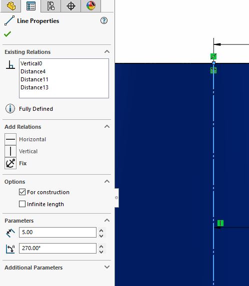
Once you click the line (highlighted blue) the line properties menu will appear and you can select for construction.
Okay we have the cutouts for the balls, now we could do something similar to the revolved boss/base called revolved cut. Instead of creating a solid body, a revolved cut will cut out the shape you select from the solid body. However, this would only give us circles internally and we wouldn’t be able to get to them like you can with the cat toy. So we have one last step before we can do that, we need to create the opening for the cats to reach in. To do that I’m going to continue in this sketch and use the rectangle tool.
You have a lot of relations you can add to a line or shape you draw. A relation is how the objects relates to another object. For example those circles I drew, I want to add a rectangular cut out and attach it to those circles. To do that I’ll draw the shape and add a relation to the corner of the rectangle that says it is coincident to the circle. That just means that no matter what happens those corners are going to touch the circle. I decide to place the rectangle 0.5 inches away from the center of the circle. Because the end points of the rectangle are coincident, the height of the rectangle is fixed and is a function of that distance.
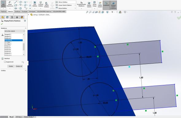
A few things worth mentioning. First all the lines are black with the exception of the ends of the rectangle. That means that they are fully defined and I cannot move them because they only have one solution based on the measurements I set. The only blue lines are not fixed because I did not set a width for my rectangle (notice there is no measurement there). I don’t need to create one as long as the rectangle extends past the part because I’m using it to cut into the part (the blue solid object we created first). I follow this process for all three of the circles. Setting the same distance from the center and the coincident relations means that they will all be uniform.
Now we are almost ready to make our cut, but first to make things simpler for solidworks, we are going to remove the overlapping parts to create a single outline of the shape we want to remove. This step isn’t needed, but I wanted to do it anyway so I wouldn’t have to select the areas I wanted solidworks to cut (I’ll show you what I mean next). So to remove those lines I’m going to use the trim entities tool. It’s a scissors shaped icon and will remove the line up to the next line. To use it you click next to the line and drag it over the line you want to cut (like scissors) anywhere the tool touches is trimmed to the next intersection so you have a single shape to cut out as you can see below.
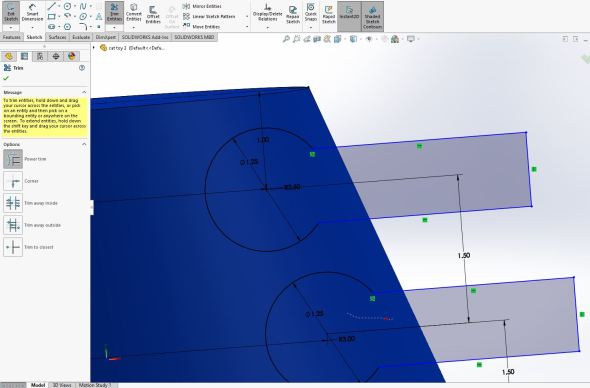
If you look at the bottom circle, you can see the line I used to cut with as I was cutting. Anywhere the line touches gets cut back to the next intersection of lines, so I could trim the overlap and end with the circle and rectangle shape combined as shown above.
Now we are ready to cut out the material and we will see that our cat toy model looks very, well cat toy like. This time while I’m still in the sketch, I click over to the features menu (top left of the shot above) and I can select revolved cut. Just like the revolved boss/base it needs an axis of revolution so I use the line I created for construction that marked the center of the object. By revolving the cut 360 degrees, we see something like this (prior to accepting it).
The revolved cut prior to accepting it. This shows the area that is being cut into and the result will make our shape much more cat toy looking. You can now see clearly why we needed to add the extra rectangular shape. This gives the opening to the cat toy, but it’s not the same diameter as the balls meaning they wont fall out.
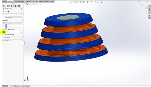
So we made our cut! This isn’t very easy to see in the program so I changed the color of it to orange, you’ll see why as we continue.
Now we have something much more cat toy like. We’re not quite done with it, but we’re close!
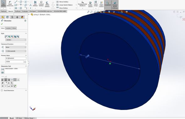
Okay so we have our shape and it looks very close to the toy, but there are still some issues. First it’s hard to tell from the photo, but there is a hole cut through the entire center, so we’re going to want to copy that! To do this I can create a sketch on the bottom face of the part. Again, if you’re using solidworks and following along (even though this is just a demo) you can do this by rotating the part and selecting the bottom face, then clicking the sketch option located in the sketch tab of the top menu.
All were doing is drawing a circle that we can cut out the inside bit. Again, I freehanded this, so I just made it the same diameter as the top. Below I’ve rotated the shape so you can see the bottom and the sides to help you orient yourself.
Our circle that we will cut out of the part
This time instead of using the revolved cut, we are using the extruded cut located in the features menu. Unfortunately, if we just do an extruded cut it will cut a cylinder shape in our part. This would ruin our part as we can see below!
This would eliminate most of our part!! We can’t do that!
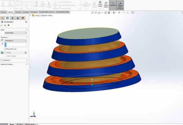
Thankfully we have a way around this. Instead we’ll use a drafted cut. I set it to 17 degrees, but really I just changed it until it would no longer cut into the outside faces.
The drafted cut option (highlighted) makes the cut smaller (by the selected degrees) so now it’s more cone shaped just like our part.
Once we’re happy with the cut, we complete it and we get something that looks like this as seen from the bottom!

The result of our drafted extruded cut
So were done… right? Well sort of, I am mostly happy with how it looks, but we still have all those rounded edges and things and ours looks more squared. So to do that we can add a fillet (pronounced fill it, said together). Click on the fillet tool (circled in red below) and I selected the top corner (highlighted in blue) for all but the bottom, the bottom I selected the bottom side of the face to make it match up with our cat toy. Then I adjust the radius of the fillet until I like the way it looks. In this case it was a 0.9in radius, the smaller the radius, the smaller the curved edge, the larger the radius the larger the curved edge.
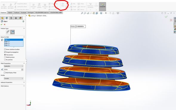
The program shows me a rough shape of how the fillet will look before I accept it (fillet tool circled in red).
So after all that, I use the fillet tool for a few more corners and end up with a very rounded cat toy that looks very much like the real thing.


You can also see why I picked the color scheme I did. We’ll go over how to do that in later posts, but this was just a (somewhat) quick demo to show you that if you can break the complex shape down into the simpler shapes that make it up, you can create very cool looking parts with minimal effort. This whole process I could do in a matter of minutes and it really looks like it should be harder than that. That’s the power of taking a moment to think about what shapes make up your part instead of trying to copy the shape directly.
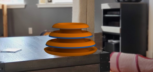
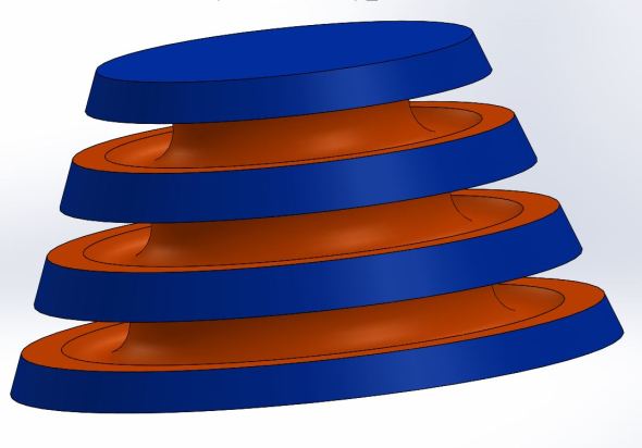
Just for fun, below is a rough render of what we just created over the original cat toy image. If you didn’t notice, it’s also the main image for this post. It looks pretty good to me! We’ll go over how I rendered this as well, but for now just know it can be done.
The fillets might have been a touch too big, but for doing most of this freehand, it looks pretty darn close to the original!
So my lovely readers, if you’re here for the long-haul (and I hope you are!) your goal for this week is to look around your home for something that has a complex shape and try to see if you can find the simple shapes that make it up, just like I showed today. Getting in the routine of doing this early will help you a LOT when we get into the actual solid modeling. Learning the tools is only half of what you need to know. We’re going over the first half and what I think is the most important half, the how to think about your part in a way that makes it easy to model!
This was a long post, maybe in the future I’ll break it up a bit, but really we made a complex looking cat toy in just a few simple steps.
With that, welcome to week 1!


But enough about us, what about you?