PC build part four, electrical fire edition!
Okay, okay clickbait headline, I admit it. If you’re here for a real electrical fire you’re out of luck. Thankfully I haven’t had an electrical fire… yet, I haven’t turned the computer on since I’ve started this project. However, a few things happened yesterday so I need to figure out my cable management before I get too much further. It’s something I’ve been ignoring and I’m finally sharing some of the mess that I’ve (somewhat purposefully) been hiding.
Computers have a lot of cables. It’s frustrating because they need to go somewhere, but one of the downsides to the case I have is that there are very few places to tuck those wires away. Basically it’s a hot mess and it needs to be dealt with, but there is good news! I’ve been avoiding dealing with this issue because I didn’t have the adapters I needed to wire the fans into the corsair icue hardware (I mentioned this yesterday). Of course the adaptors were misdelivered so I was disappointed because I really want to finish this build and I need to get those fans wired in!
Thankfully, the neighbor brought over the package yesterday, apparently it was delivered to his mailbox and not mine so I now have adapters!!
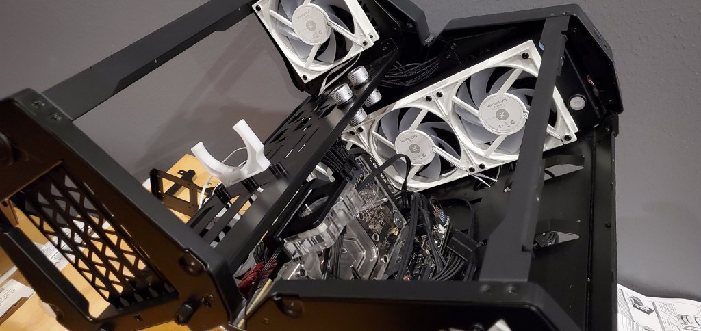
Which of course means we can deal with the mess of wires now. Or at least start planning that far. Now technically the wires came last, so maybe we should start from the beginning. With the radiators in place, the fans set, the cables run (at least on the mostly visible side) and the water blocks placed on the graphics card and CPU, I had only one more piece to place before I could run the tubing. That would be the pump, which I have yet to show a photo of, but I’ve pointed out where it’s going, where the white u shaped bracket is placed now (below).
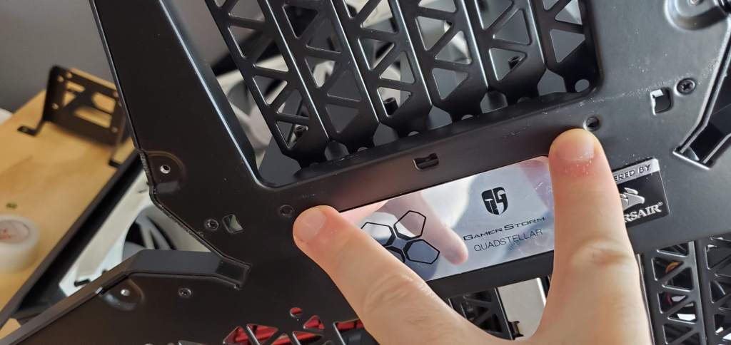
Yet, to install the pump I needed to once again get creative with my modding. The pump has a bracket that needs to be screwed down, but I needed to drill the holes for the screws to screw the bracket down. Thankfully they send a template sticker (literally a sticker) that you can use to cut the holes with. So as with everything I’ve done, we test fit the pump, place the sticker, test fit the pump, adjust the sticker, and repeat until it’s where I want it and so all four holes are over solid metal and not some of the precut holes in the sheet metal.
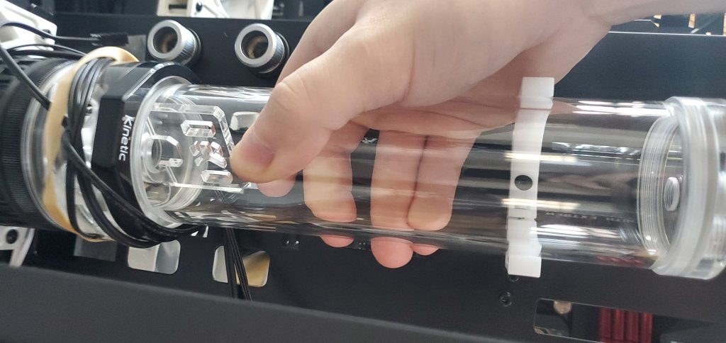
Above is a photo of me test fitting the pump. This was taken after I placed the sticker to cut the holes and I just wanted to verify that the sticker was placed in the correct place. I’m angling the pump slightly so the liquid settles by the pump inlet instead of the other end of the tube. Don’t worry, I have better shots of this, so hold tight.
Now that we have
Four screws hold this in place, these two 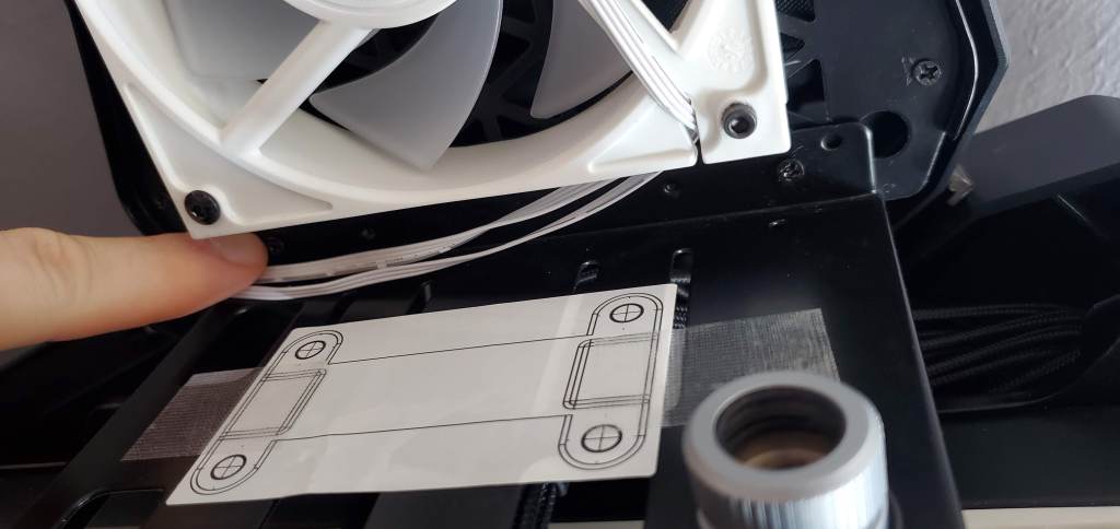
Then two in the front 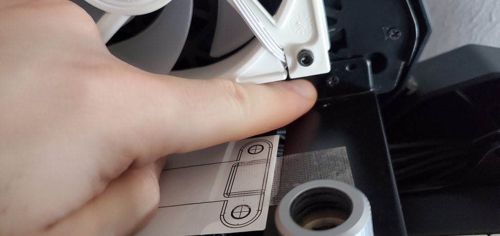
Then two in the front 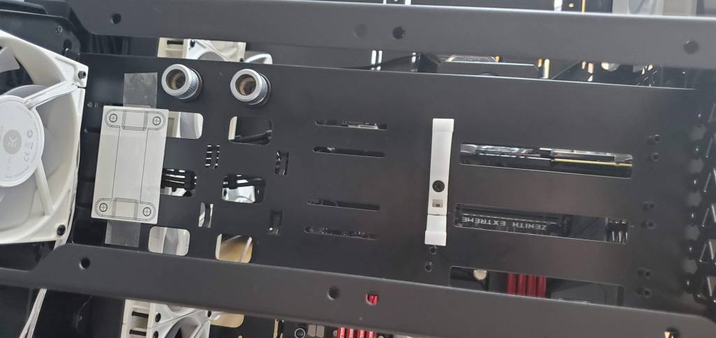
A shot the piece that I’m going to be mounting the pump to.
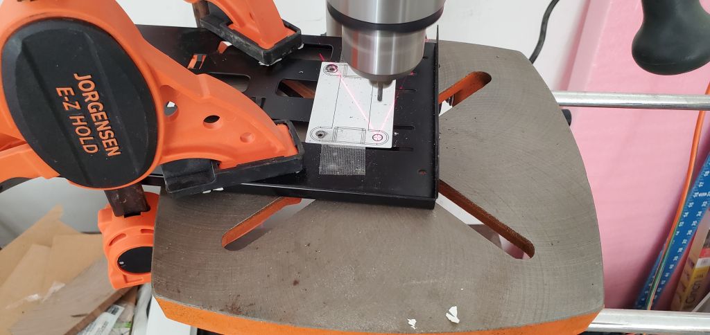
Now the problem became how to make the cut. Embarrassingly, I didn’t have metal bits that small small so I wasn’t sure how to make this cut. I settled on using a masson bit and the drill press. Failed attempts would include, dremel and drill. Luckily I had the drill press (it’s been a great purchase I got an amazing deal on). So I clamped the part down, put the bit into the drill, and cut the holes. As usual, hearing protection, eye protection, and foot protection are all required. You may notice the bit is very short, I placed it pretty far into the chuck to keep it from walking after the first cut I made the bit tried to walk. Walking means exactly what it sounds like, it starts to move away from the hole you want to cut. Reducing the length of the bit and increasing the speed fixed the problem. Remember, when cutting sheet metal, use a metal file to remove the burs or you get something very stabby.
The first cut is the deepest… err hardest. 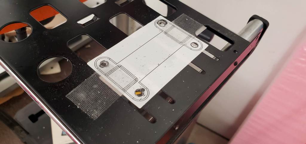
Everything trimmed and filed
With the bracket cut, it was time to install. Of course cutting took a significant amount of time so now I’m somewhat behind my original goal, but we’ll get to that. Installation was simple, it was just the reverse of what I did. At first I thought it would be easier to install the pump bracket once the metal piece was back in place. This turned out to be obviously not the case, about 20 seconds after I put it back on I realized it would be easier to get the pump bracket installed with it off the computer, so back off it went and while I don’t have during photos (not really worth showing anyway, it’s just me screwing some things together).
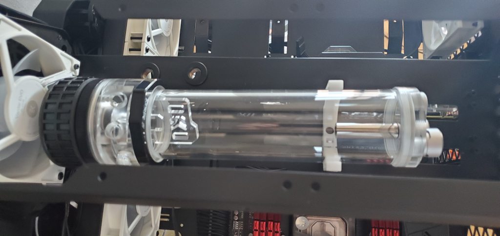
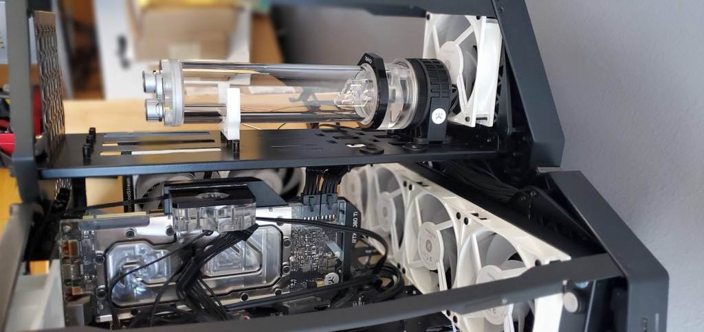
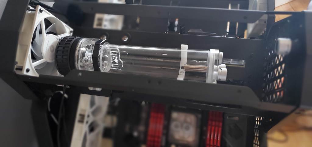
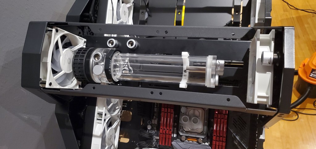
The length of the tube (where the extra liquid is stored) is so long I was worried that just bracing it using the pump bracket would cause problems. For example if I moved my computer and the pump flexed it could crack the acrylic tube, which would obviously make a huge mess. To solve that problem I repurposed that white bracket, it’s technically designed to just hold extra tubes since the more liquid in the loop, the higher the heat capacity and the more stable the temps. Thankfully it worked out perfectly here for my purposes. I had to mount the bracket to one of the risers for the pci holder, but you can’t really see it and it makes the bracket look almost like it’s floating. In the end it’s good peace of mind, but it also doesn’t look bad.
You can also see in the last two photos, I installed all the fittings into the pump and reservoir. The pump (left) has two inlets and one outlet, so I sealed off one of the inlets (since the inlet is the reservoir). The second is being used as a temperature sensor (you can almost see it on the bottom side of the pump in the last photo, it’s a different color than my fittings so I wanted to hide it). This will let me monitor the temperature of the coolant. Then I installed the fitting so I can run the tubing. The reservoir has three inlets, one of which I sealed off, the top is being used to connect the fill plug. The bottom is my return line for loop, I used the bottom because I want the fluid to get pumped under the fluid line or you could end up with splashing if the return line is above the fluid line. Unless you want your loop to sound like a waterfall or fountain (I do not), it’s something to keep in mind when planning your loop.
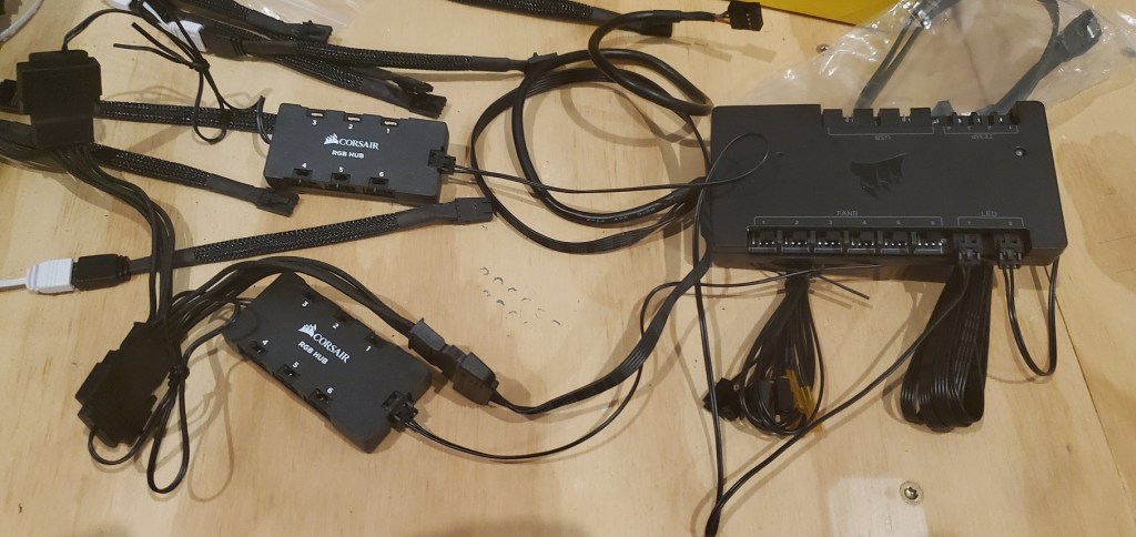
Now for the wiring. As I mentioned my neighbor brought over my package. I guess he doesn’t check his mail often because it was delivered Thursday, but whatever at least I have it now. Here’s the hardware for the icue system. It will let me control up to six fans and 12 RGB sources. It also has four inputs for temperature sensors and two for USB. Not sure what the USB is doing there, but it’s there. I should probably read up on it to see if it’s useful, but the rest of the stuff is going to be used.
Corsair uses a… how do I put this? Non-standard rgb input. It’s not a huge deal and it’s probably because they really want you to use corsair products with their icue hardware, but I needed high static pressure fans (or rather wanted) and they didn’t have anything that fit the bill so I went with EKWB fans (seen in basically all the photos). So I needed the much talked about adapters! Below is a shot of the adapters. They are the black worm looking things that I’ve plugged into the RGB fan ends (white wires).
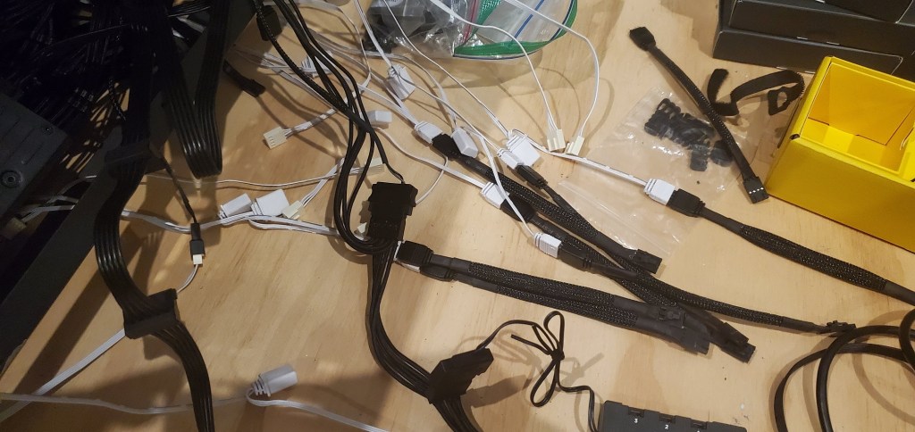
Since I’m me, the inputs are numbered, so I can make a mental note (or a blog note) of how I arranged the fans. I wasn’t about to plug everything in at random because I want to make life slightly easier when I go to turn on the computer and set up the icue lighting. So once I had everything plugged in we have this…
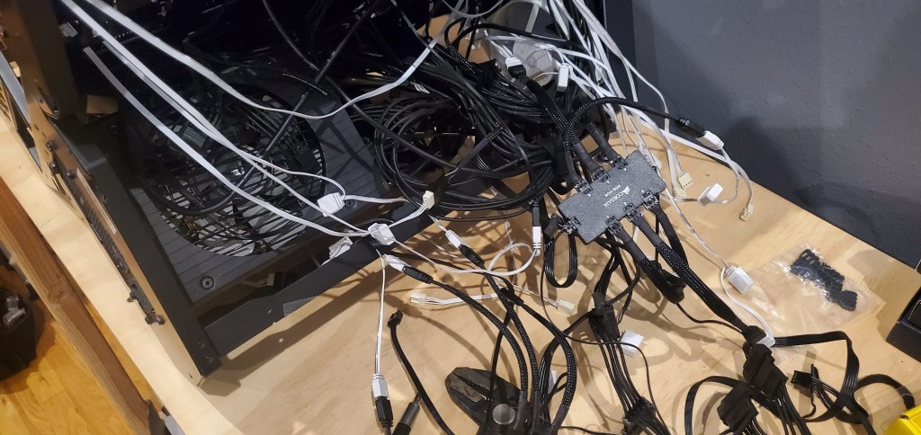
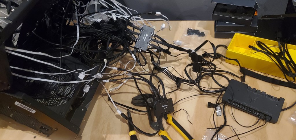
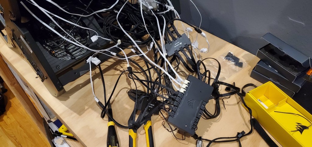
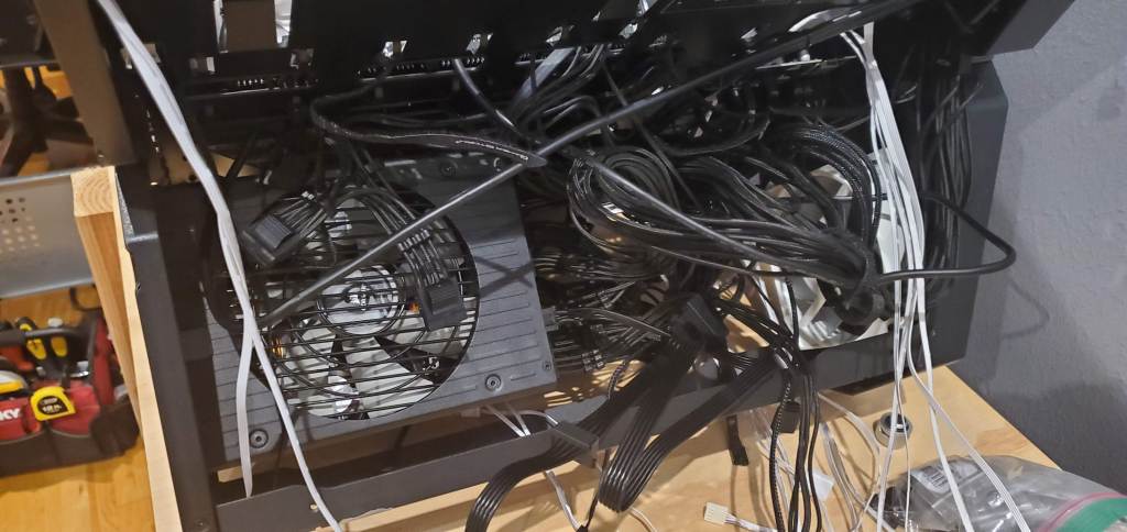
Welcome to the other side of the computer! Almost anything that needs power gets routed to the power supply (the black box with the grey fan inside in the computer). That’s kind of why it looks like this section is just an explosion of wires. My goal (should I feel adequately caffeinated) is to organize that mess as best as I can to make it at least mostly presentable when people look into the glass viewing port, because yes there is a view port installed on this section, I assume for symmetry purposes, but it makes my life a pain because it makes the cable mess I want to hide very visible.
Since I have a lot of competing things going on today, I’m not sure how much I can get done. I would like to start bending the tubing, so I may get at least a bit of that done, but with all the loop components in place, I’m free to bend whenever I feel up to doing the work. What I would like to do before starting that is get the wire situation sorted out before I start to ensure that everything is done and I can just bend, leak test, fill, and go. That feels like a better order of operations to me, so today may be boring cable management, which means you may not get another computer update until next weekend (hopefully the finale!) since I’m pretty busy during the week these days.
So yeah, maybe an update tomorrow, maybe not, but hopefully the final bits will get done and we can get this thing back up and running. I need to use it badly to get some work done, so the clock is ticking!


But enough about us, what about you?