PC build part seven, the tale of the leaky loop
Well I’ve done it… mostly. The loop is finally complete and I’ve pressure test it. There were of course some technical difficulties, which I resolved, but I also caused because I’m an idiot. I wasn’t planning on making another computer post until I had the thing turned on and finished, but today I want to tell the story of how a $20 USD part saved my computer.
As us always you can find the full story in the computer rebuild category. I keep forgetting to put that in my posts… oops. So one more time from the top, computer overheated, which was bad. Swapped out the AIO watercooler for another AIO because I assumed I just had bad luck. Thus in less than two years I had broken two AIO watercoolers (or rather they clogged). So this is part seven of my custom hardline watercooling loop build. It’s been going slow since I just started my new job, I’m in school, and because for the past month my mental health has been pulled through a meat grinder and I’m barely holding on.
Enough of the depressing stuff though, let’s talk about the build. Yesterday I had one (technically two) bends left to make. The long run, which was going to be the hardest and the forgotten inlet port bends to connect the fancy fill plug (I installed here), to the inlet for the reservoir. I almost forgot about it, but realized my mistake after I bent the long run I had.
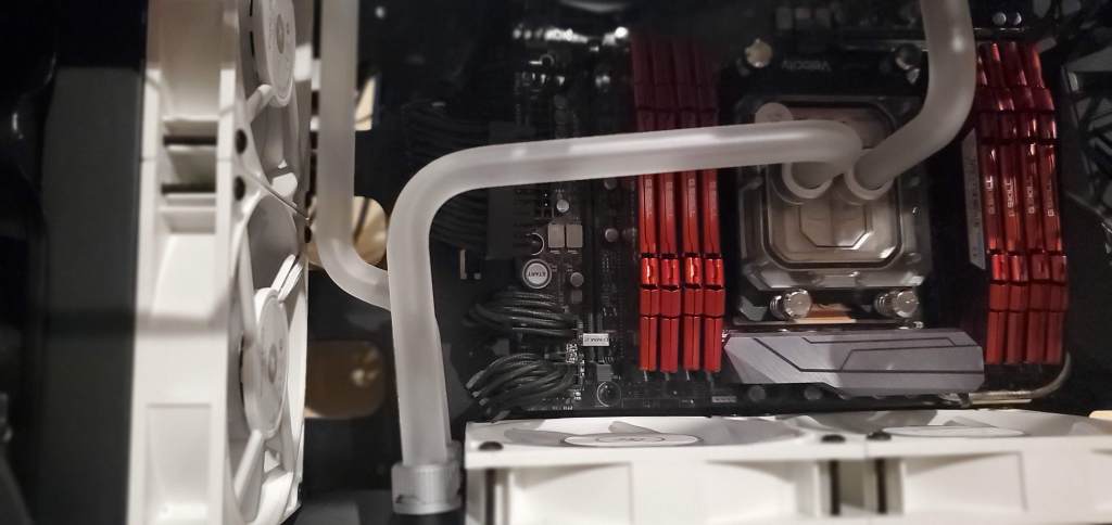
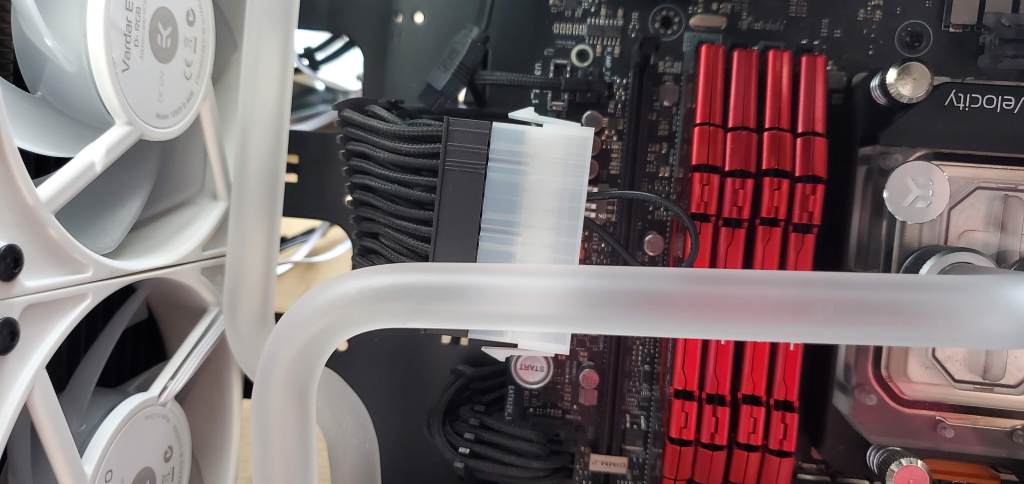
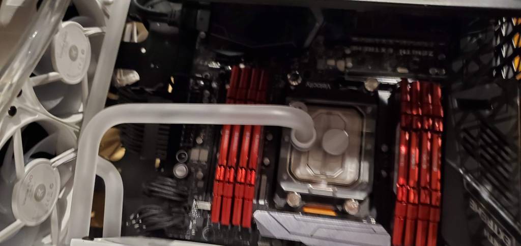
So the story for the long run goes like this, I need to connect the two radiators together on opposite ends of my case. Simple enough, one 90 degree bend and I’m there. The catch? I run uncomfortably close to the power cables for the motherboard, which could press against the tube or do all sorts of weird stuff. I could run the cables around the tube, but I feel like that would look ugly, so instead, we’re doing it the hard way. Which is of course to say, the right way.
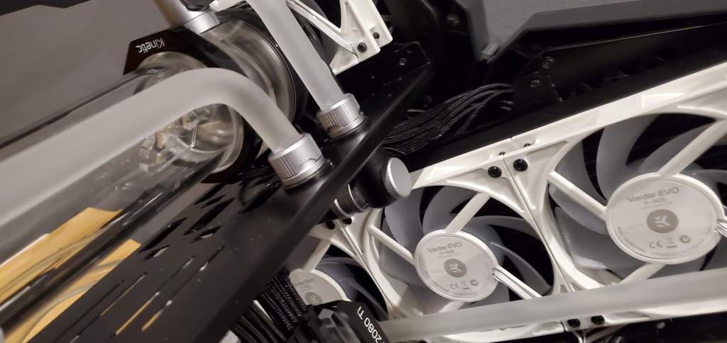
Since I couldn’t run it straight to the radiator, I decided to add two 90 degree bends. This would offset the outlet from the small radiator and I could run the line closer to the 480mm radiator all the way up to the inlet for it. That was where the trouble came in. I don’t know if I discussed it yesterday, but I attempted this twice and failed both times. The 90 degree bends need to be very close to each other or I would run into the radiator (which I kept doing no matter how close I made the bends).
This time I decided not to take any chances and put the bends right next to each other. Easier said than done because when you apply heat to the tube the bend will relax so I then had to deal with two 90 degree bends and both of them not wanting to stay where I put them. I’m not going to lie, in the end it wasn’t perfect, but I did it. As a bonus the angle that I ended up with matched almost perfectly the off angle of the outlet for the small radiator so the two tubes line up and basically look correct. Happy accidents!
Next I needed to add the bend to the outlet from the big radiator and I ended up cutting things slightly to fit properly, but it all worked out. I’m slightly disappointed I couldn’t get the bends (above) to line up with each other, but hey it’s my first time bending tubing.
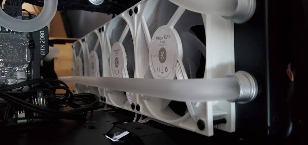
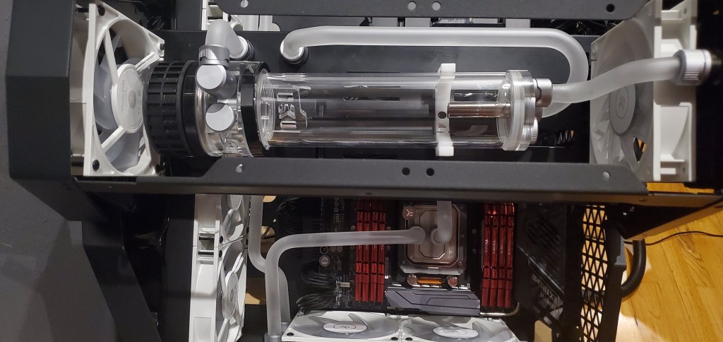
Thankfully as far as I can tell via eyeball (which is good enough for me) the tube runs parallel to the radiator, so it doesn’t look weird (again at least to my eye). Actually, digging through my photos it seems that I took a somewhat artistic shot to show it was parallel. Not bad, right?
Lastly I needed to bend the tube for the inlet port. That took a couple attempts as well, I think I got it right on the third…? attempt, the first was close, the second was worse, but the last one worked out the way I needed it to and we now have the last tube bent and in place!
The fill line! 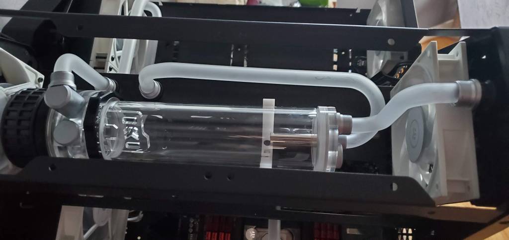
Fill line from the top!
This was exciting because it meant I could put the fittings on and tighten it all down. In short I was finally done! Except things are never quite that easy for me… but first the full vanity photos of the finished product!
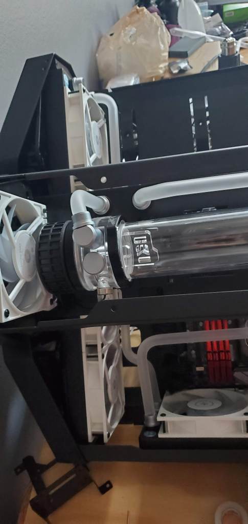
My quick drain plug (attached behind the tube at the t-fitting) 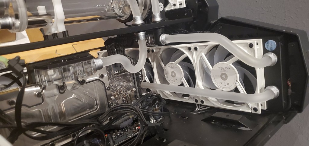
All the fittings tightened down 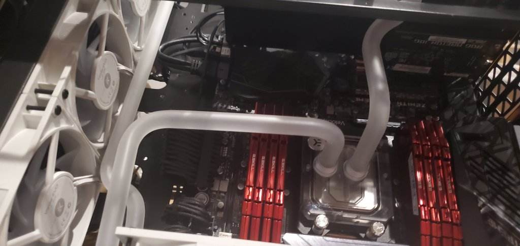
More fittings! 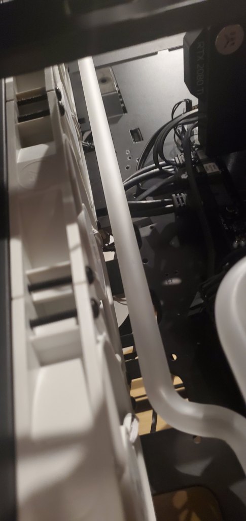
Random shot 
Another random shot 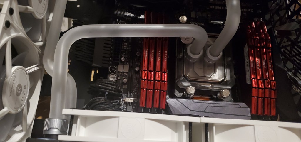
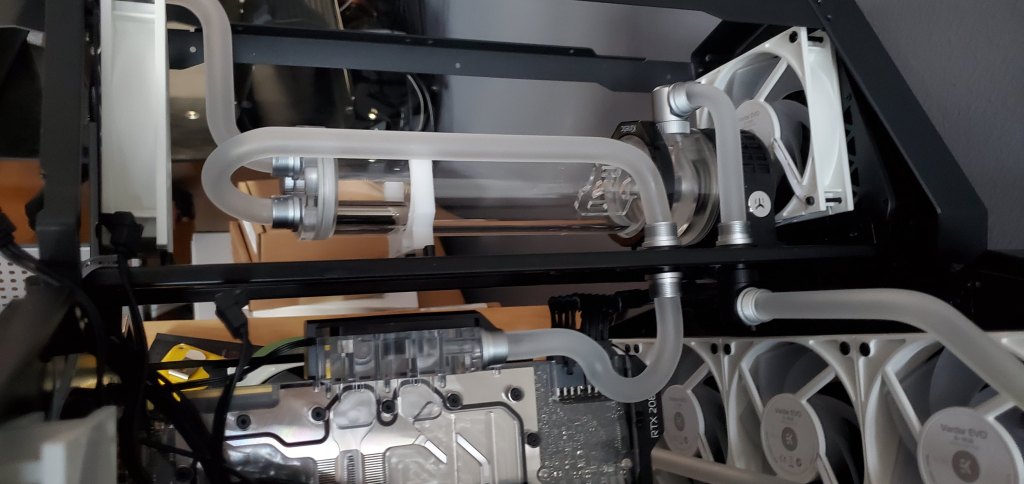
Still more fittings! The full view 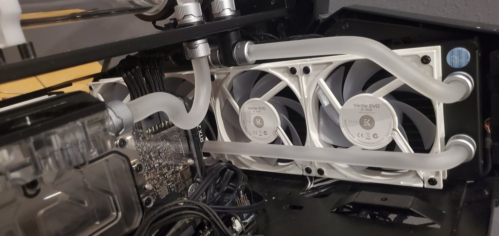
This was the view I was really proud of 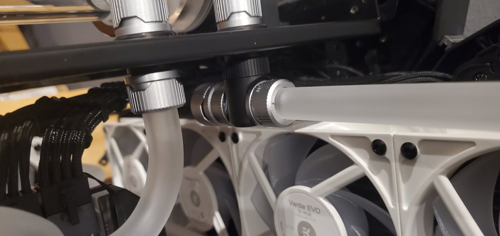
Fittings on this bit too! (notice they were missing on the first image).
Let me just say, this was a fucking journey. I’ve never spent so much time and effort on building a computer. I want to say it was worth it, but it’s been a frustrating experience. It will probably be worth it once it’s finished and turned on and it was fun for the most part, but nothing is more frustrating than getting a bend ALMOST perfectly where you need it… almost. So as a reminder that this was not easy and if you jump in, I would advise plenty of time to dedicate to this (multiple days would be best, trust me), and buy plenty of tubing. I am happy to say I just barely had enough to finish this build, but not enough to redo any of the bends that were slightly not how I wanted them. As for the scrap pile, well I gathered it all up and took a photo.
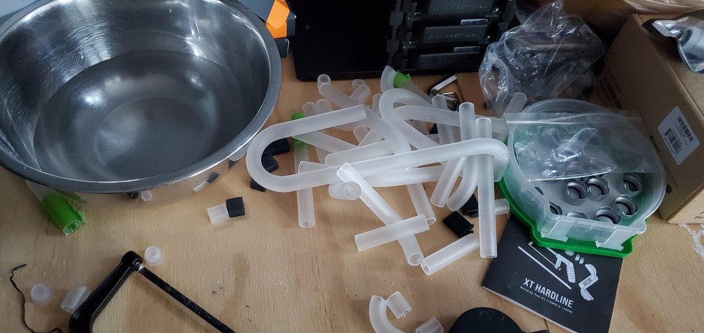
Quick side note since I just remembered from the photo above, inside the tape container I have all the fittings for the tubes, there is a small black gasket that slides over the tube and gets compressed when you tighten the fitting. Keep track of those damn things, they are easy to lose. Specifically I lost two of the o-rings to my rig and I cannot for the life of me figure out where they went or how they disappeared. They literally vanished. It’s the dark forces at work inside my computer.
Literally no clue where they went, it reminds me of all the sockets I’ve lost working on cars, they fall into the abyss never to be heard from again and no matter how much of the floor you can see through the engine bay, they never seem to hit it. Anyway back to the story at hand.
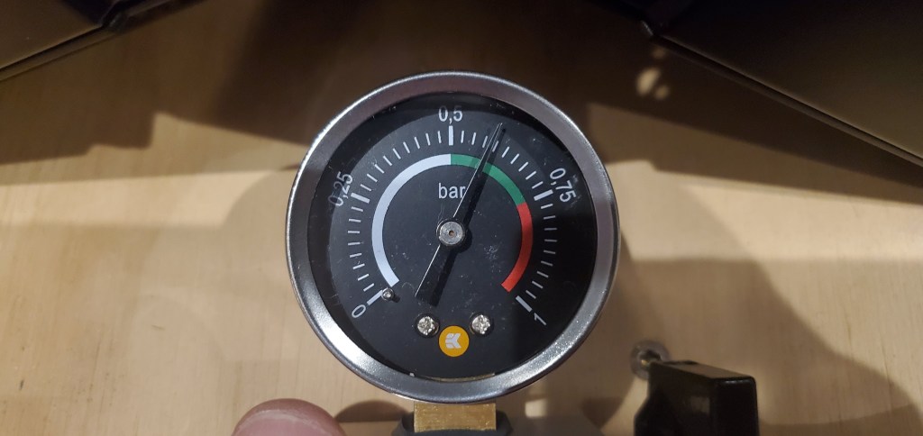
An ounce of prevention and all that. Reminder, water and electronics don’t mix, so we contain the water and keep it seperate from the computer when we water cool. I COULD add fluid to the pump, circulate it, and run it for a few hours to see if we had any leaks, but there is a much easier way to do this and it’s using a pressure tester! Using the drain valve I installed (seen in a few of the photos above of the t-fitting) I connected some soft tubing (it’s almost as if I planned for this) and connected my pressure testing gauge. The cost for this tool? Roughly $20 USD. The soft tubing and fittings cost extra, but I will eventually use the tubing to drain the loop when it comes time to swap the coolant (again every 6-12 months depending on how stupid brave I want to be).
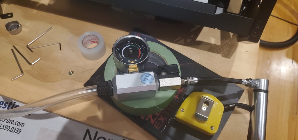
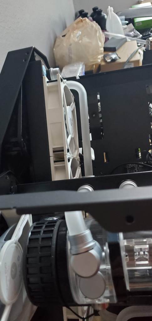
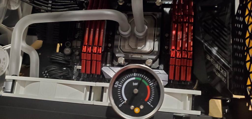
In the photo on the left, we have the soft tubing connected to the pressure gauge and on the opposite side next to my tape measure we have the pump. It literally works just like a bicycle pump, so easy to operate. This was roughly 10pm last night and I was hoping for a victory before calling it done for the day. It was not meant to be. The needle needs to get to the green range, the valve closed (so it doesn’t back bleed through the pump) and left to sit for ~15 minutes. You could go longer, but 15 minutes seems like far more time than needed to me even for a very slow leak (as someone who worked on cars/tires/etc, leaks are kinda my thing).
The problem became very apparent when I got even close to the green, I turned the valve and the pressure started to drop rapidly. It wasn’t a small leak, it was a big one. After about 20 minutes of panicking, checking my fitting tightness, and retrying to no success I was about to just sell the damn thing and let someone else deal with it. Kidding, but only slightly.
This is where my engineering education came in handy (okay, probably not, anyone could’ve come up with this solution). I decided to systematically check my loop for leaks. I assumed one of my tubes was either not seated properly or cut the gasket somehow. I’m an idiot, these things happen. Actually it turns out the problem was the fact that I’m an idiot, but we’ll get to that in a moment.
So I started by checking the obvious, the first bends. Doing that was pretty straight forward, I just had to block off the inlet and outlet from the pump at the pass-through fittings. Once I did that I brought the system up to pressure and left it for ~10 minutes. I wanted to be safe.
When I came back I compared the photo I took of the gauge when I first pressured it up with the current gauge and everything was good. It turns out I’m not completely useless.
By now it was getting late, but I said screw it, I was going to get this damn thing figured out. So I decided to add the graphics card to the loop I’ve already cleared and test again. This was were I found the issue. The pressure would not hold and it was then I found the culprit. The graphics card was the problem so I had to yank it completely out of the system to diagnose. Later I would realize this was dumb and I could’ve just checked the obvious while it was in the system, but I had assumed the issue was the new flow gauge that I added because there was a problem with the seal when I assembled it. Sometimes our brain gets stuck on something and we ignore the obvious, I was ignoring the obvious.
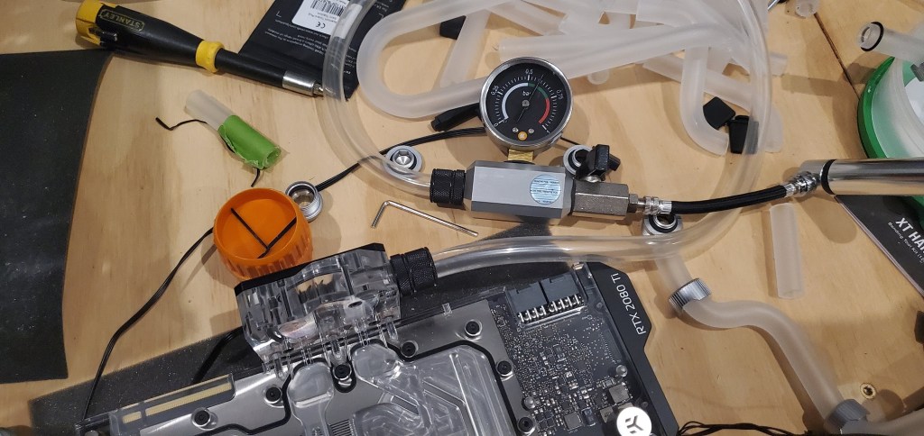
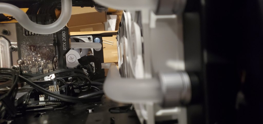
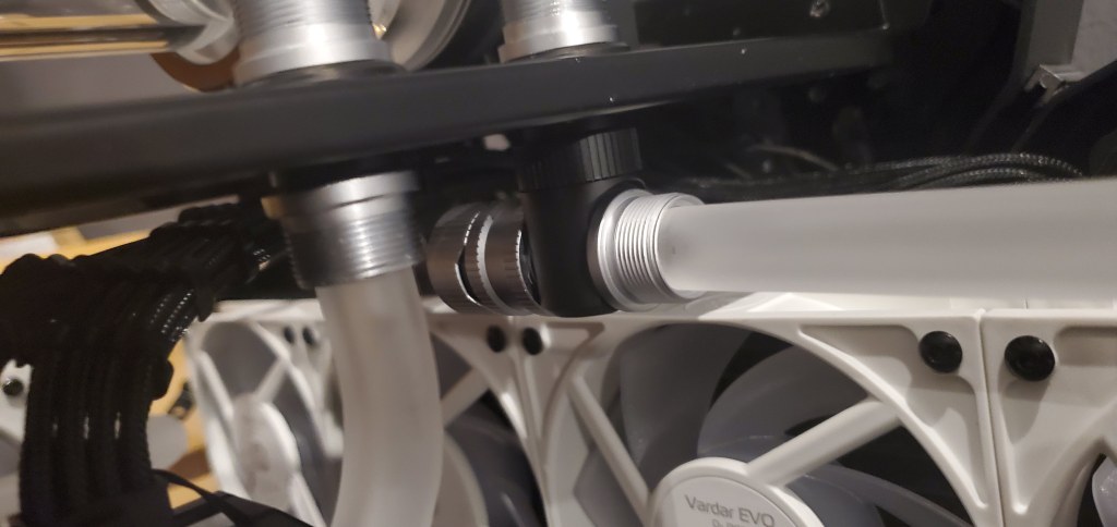
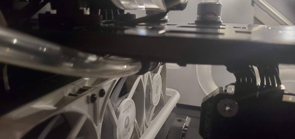
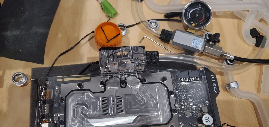
So I popped off the flow gauge and inspected the gaskets. See the black ring around the graphics card, that’s a gasket, there were two very small ones that connect the block the pressure gauge goes into to the graphics card itself. That was where I thought the problem was because why would it be anything else? It turns out that wasn’t the issue. The issue was the fancy fitting I put on the back of the damn thing! Seen (barely and very poorly) in the photo below at the top (the circular bit at the top which I’ve marked with a red arrow).
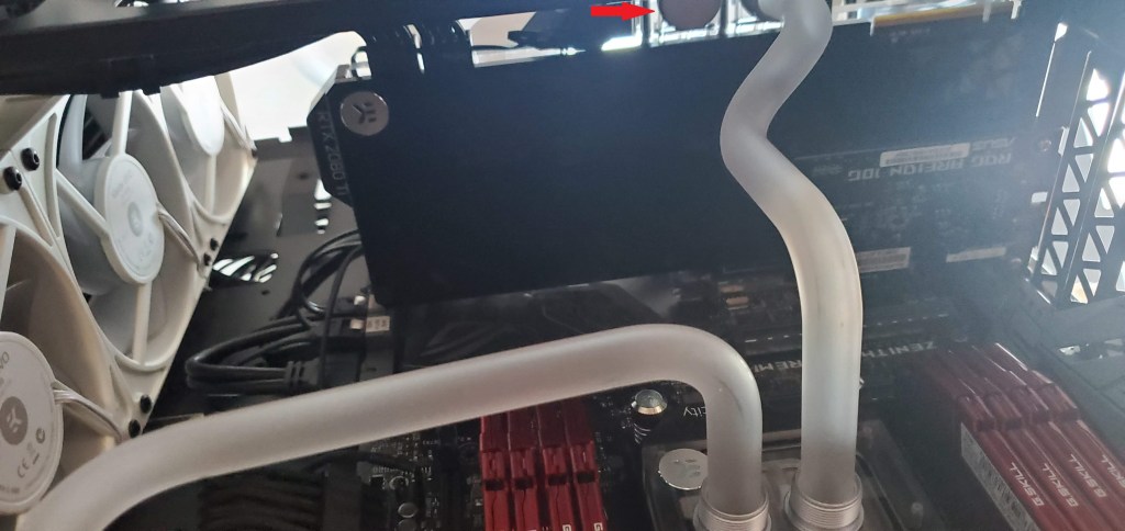
I caught the problem when I was inspecting the block and noticed that the two fittings I used to seal the back were the same, but the plexiglass made the seals look completely different, one had a clear black ring the other did not. I unscrewed the one that did not and it turns out the hand fitting probably isn’t designed to go into that type of recessed plug, so I put back in the old fitting, pressured up the system and after 15 minutes, wouldn’t you know it, I still had pressure.
Just to be thorough I connected everything in the loop back together minus the graphics card and tested the remaining portion of the loop that hadn’t been tested yet (basically everything but the graphics card).
Everything held pressure and suddenly I didn’t feel too bad about my skill level. So I put the GPU back into the computer, did my cable management thing, connected all the lines and gave the system one final pressure test with everything connected. This time I walked away for about 20 minutes (because I had other things to do at this point). When I came back I looked at the gauge and we still had pressure!
And that my friends is the story of how a ~$20USD part saved my computer build and kept me from making a huge mess in the process. The whole ordeal took roughly two hours, but I disconnected the pressure gauge, closed off the drain port (an important step for sure!) and packed everything up. Since at this point it was after midnight, I decided that was more than enough computering for one day and I could finish this later.
Now I’m not 100% sure when I will add the fluid and get it all back together and turned on, but it probably won’t be today unfortunately. I’ve got far too many things going on! The good news is the computer is (mostly) done so the next post on this saga will be the exciting conclusion. Afterwards I’ll probably write a condensed guide with information for anyone else who wants to take the plunge. This took a lot of time, effort, planning, money, and work, but at least I can say I built something cool (pun intended).
I’m hoping the next few steps will go smoothly. Basically the order of operations is to fill the loop, run it for a bit to get the air out, then turn on the computer and mess with all the new RGB fans I’ve got to play with (both fan curves and color schemes). Once I’m sure it’s all working properly, I can throw the covers back on and that will be the end of the story basically!
I should have the final installment of this in the next few days, so I’ll probably post it over the weekend so it will give me a chance to get everything else done and show off the final, final setup. The catch is this assumes everything goes smoothly, which is never a good assumption around here, so stay tuned and hopefully we’ll have something cool to look at shortly.


The photos of the open computer and parts gave me a little anxiety… 😐
LikeLiked by 1 person
October 13, 2021 at 3:38 pm
Haha yeah I’ve been building computers for what feels like forever and it gives me anxiety having it open too.
LikeLike
October 14, 2021 at 9:47 am