Day 313: Solid Modeling – Week 3
This course will all be taught using free software so have no fear, you can do it too! For those just joining us you can find all the posts in this series in the handy Solid modeling for beginners category. For the past two weeks I’ve been going over best practices. The reason is the tools are straightforward to learn, but how we use them is what separates someone who is learning from someone who is a pro. I have had some thoughts about what I wanted to cover this week for that reason, but this week we’re making something and by me we, I mean you! First, let’s do a quick recap of what we’ve learned and we can get started.
For the past two weeks we’ve been talking cat toys, well a particular cat toy. The reason is the shape was nice and complex. We broke it down into simple shapes and it gave you an idea about how to start seeing objects for what they are, basic shapes combined in different ways (week 1).
Then I explained in week 2 that we didn’t need to take all the steps we did in week 1, we could create the same thing in one single sketch, and we did! However, then I highlighted why that is a horrible idea and explained that editing that single sketch would be a nightmare. In the end it’s best to break the steps you use to create a part into smaller pieces so you could go back and edit them.
This week I was debating about getting started with the software or giving another demo about how to think of a complex part in smaller, simple shapes. Well you’re in luck if you’re itching to dive in because we’re going to start from the beginning with our free to use software sketchup! You can also download a 30-day free trial that runs on your computer and use all the tools they have, but this week we’re using the internet based version because we’re going to dip our toes in slowly. I’m also going to be cross referencing my go-to software solidworks. I’m doing that because one, I’m teaching a solidworks specific course, and two it’s a great way to see that all solid modeling software is basically the same, it’s just a matter of how they organize the tools.
With that let’s introduce the concept of the plane. If you’ve taken a geometry course you know that a plane is a two dimensional flat surface (we’re talking euclidean geometry here, no need to get fancy). It has zero thickness and to put it simply defines a left and right and up and down. Let’s look at what those planes look like in both solidworks and sketchup. First solidworks. In a three dimensional world we need three planes! So by setting them visible, we have a front plane, top plane, and a right plane. The names are just that, but they help us orient our object in space in a way that would make sense to anyone looking at it. So if we wanted to see an object from the top view, we could use the top plane.
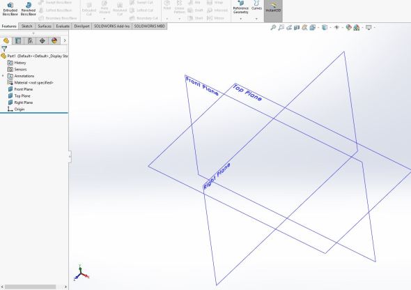
The three planes of solidworks, we have a top, front, and right plane. Normally these are not visible, but I turned them on so we could see them.
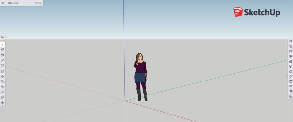
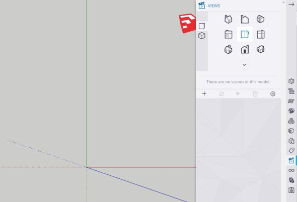
Sketchup is a different beast all together! When you open it for the first time, you’ll see a very different world. In this case we have our axes defined, but we don’t get to see a physical representation of the planes like we do in solidworks. That doesn’t mean they aren’t there, it just means sketchup doesn’t show them to us in the same way. That’s okay though, notice our axes have different colors to help us orient ourselves. Instead of using front, top and, right, sketchup color codes the axes.
Welcome to the world of sketchup! The person comes predrawn when you start a new file and it helps you orient yourself in the world view we see here.
That doesn’t mean sketchup won’t allow you to switch views though, so let’s talk about camera placement! In solidworks you can switch to a front view, right view, or top view very simply. By holding control+1 you get a front view, control+2 gives you the front view from behind (behind view), control+3 gives you the right view, control+4 gives you the right view from behind (so left view), control+5 will give you the top plane, as with the the others, control+6 gives you the top view from behind (bottom view), control+7 will give you a 3 point view (similar to the one I’m showing in the solidworks planes image.
Sketchup let’s us do the same thing, but the free version doesn’t have the handy quick keys. For that you need to activate your free trial and download the software. Never fear! We have a way to do it though, so let’s look at the menu for this!
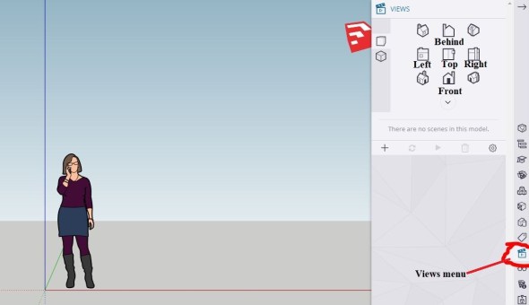
Entering the views menu (found on the right side of the screen) will give you the pop out options seen above. I’ve labeled the main views to make it easier to understand how it works, but you have some isometric (3-point) views that are the combination of the three views nearest to the icon. I didn’t label them because it would’ve taken up too much space and made it hard to read.
Okay, so now you have an idea about navigating. Using the views menu the camera (the view we have) will change according to what you select. When drawing in three dimensions it’s important to be working in the view parallel to that (so looking directly at the plane) or you will inevitably draw something incredibly far away from where you meant to place it. That’s because we only see in two dimensions on a computer monitor, our feeling of the third dimension is based purely on scale so if I were to draw something at an odd angle there is a good chance that I’ve placed it in a bad spot and it only looks correct because the scale is what we would expect at that view. The second you change views you’ll notice it is nowhere close to where you thought you placed it. Trust me on this, I’ve done it too many times to count.
Okay before we get into how to draw (I know this is boring, but you really need to know this) let’s look at one more way we can move our camera view around. Now in solidworks if you’re using a laptop you can use the arrow keys to move the camera a fixed amount left, right, up, or down. On a PC or with an external mouse, you can hold the center scroll wheel and drag. Since you can’t see that very well in photos, let’s look at the way we do this in sketchup.
With sketchup the same thing applies you can use the center scroll wheel of your mouse to rotate around a fixed point just click and drag. You can zoom in and out by using the scroll wheel (rotate forward or backward).
Note: Zooming in and out using the scroll wheel is super useful and both solidworks and sketchup use the same functionality. That is to say that you zoom where your mouse cursor is placed. If you are zooming into something far away, the zoom feature zooms faster. Once you get close to the object it slows down so you don’t zip past it. It’s very useful, but you need to remember it is based on where you place the mouse cursor!
Unlike solidworks however, you can access these tools in the menu! Let’s take a peak at what other tools we have! On the left side of the screen we have a bunch of tools. Most of these have the little carrot (the > symbol) that signifies there are tools hidden in the menu. If we click the orbit menu (found at the bottom) you get a little pop out with all the tools hidden in that menu.
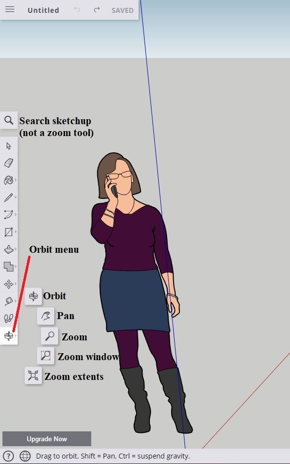
Here’s what’s hidden in the orbit menu. When you click it you get a pop out with the tools shown above. I’ve labeled them to make it easy to tell what you’re looking at. Notice at the top you have a magnifying glass, that isn’t a zoom tool! That’s just the search sketchup tool, which is useful, but not what we’re talking about here.
We can get into the other menus next time, but today I want to introduce some of the tools and get us started with solid modeling! That said, let’s talk about how we draw things. In solidworks, in order to draw something you need to select a plane, go to the sketch menu and select sketch. Shown in the series of images below.


Sketchup is a little different, we don’t have sketches exactly. They have a feature tree just like the one we have above. The feature tree is the list of things in your part. In solidworks that includes history, sensors, materials, all your planes, your sketches, etc. It also is in an order, the things at the top of the tree were drawn first, if I were to create a new sketch, it would be placed below the sketch I just created. Basically order matters and it’s in the order of operations you performed. We can change that after the fact, but we’ll get into that another time. Back to sketchup!
Sketchup lets you draw without creating a sketch explicitly. I’ll show you where the feature tree for sketchup lives in a moment, but let’s introduce our drawing tools so we can draw something and you can feel like a solid modeling ninja. First select the stock character drawn in sketchup (seen above) and hit the delete key. Now we have a clean workspace! Using the camera menu we just covered, select the top view (shown below)
Your view should look something like this now.
Now we can draw something! To do that we have a few options, but let’s start simple. Let me introduce two tools that will help you in your solid modeling conquest. This time I’ll introduce them in sketchup first, then solidworks. First the line menu, this lets you draw lines or splines (curved lines). If you click on the line menu you’ll see two options, the line tool and freehand, freehand is literally what it sounds like and if you are adventurous, now is your time to shine!
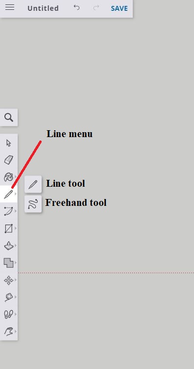
The line menu, you have two pop out options here, the line tool and freehand. Freehand is self explanatory and if you’re feeling adventurous, I say go for it!
Next we have the rectangle menu. This is probably one of my more used menus. The pop outs for this menu include the rectangle tool (of course), but also the rotated rectangle tool, the circle tool, the polygon tool, and a text tool. We’ll go over all of them in (somewhat) detail, but for now just know they exist! For this tutorial we’re going to make a simple cube. Boring? Maybe, but once you do this you’ll be able to draw all sorts of things and a cube makes it easy for me to highlight all the features you’ll be able to use.
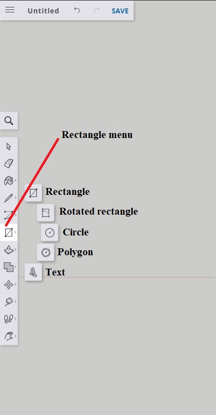
The rectangle menu gives you a bit more options. You can place all sorts of shapes, but you can also create text, which is super helpful!
First let’s look at the tool placement in solidworks. You shouldn’t be surprised, but it’s basically the same thing. The menu is more condensed so I took the time and broke it out so you could see all the features. There are some that aren’t readily accessible in sketchup, but when we compare the cost, IE- free vs. a lot of money, the tools are basically the same.
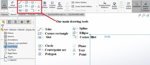
When we create a sketch in solidworks we get these tools, notice the carrot, there are other options for these tools, but they are just change how we define our shape, for example we can create a three point rectangle instead of 2 points, same for the circle. It’s just an added layer of flexibility to do things with, but for those of you just starting out, you don’t really need it.
Now it’s time to draw! To do that in sketchup (and solidworks frankly) select the rectangle tool. Move your cursor where the axes meet up it should snap to the (0,0,0) point (the origin) click it and drag it to the right, you’ll notice at the bottom right corner you have the dimensions of your rectangle. Now, I’m from the U.S so don’t hold it against me, but I’m using inches. I’m making this a 2 inch x 2 inch rectangle. You can do this in metric and it’s 50.8 x 50.8 mm or just go 50 x 50 mm and you’re good. Once the measurements window shows the correct dimensions, click again and you’ll have a nice rectangle that is now filled in.
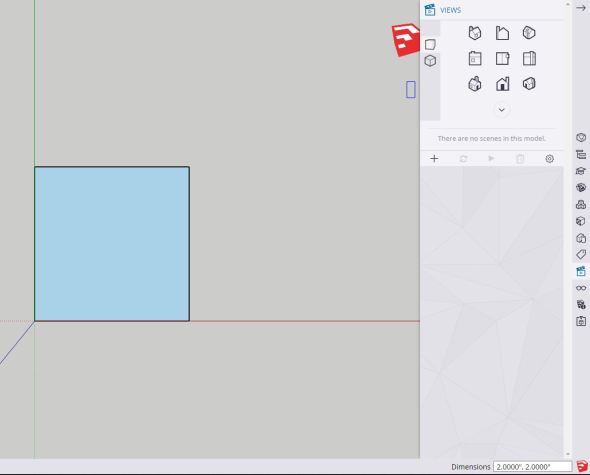
Notice I’ve started at the origin (where my axes all meet). The dimensions at the bottom right say 2 inches by 2 inches. If you’re having trouble with getting it correct try to zoom in or out to adjust how hard it is to snap to the correct size and it will snap at regular intervals.
In solidworks we have a different way of doing this, but only slightly. Once again you can snap to the origin by moving your mouse cursor to the drawing if the axes (red L shape) and you just draw your rectangle however you want. Then you’ll select smart dimension and enter the 2 inches x 2 inches ( 50mm x 50mm) here.


Notice in both the shape is filled. This is not by accident, when we have a closed shape it will fill in the space inside that shape. If it is open then you will not have this shading. You don’t need a closed shape to create with, but since we’re just starting out, it’s a good idea.
Okay, all that work and we’ve only created a shape, what gives? Where’s our cube!
Now we can extrude our shape. Extruding just means we give it a thickness, so we can turn a circle into a cylinder, a square into a cube or a bar shape, basically any shape we want, but (for now) we can only do that in a straight line. So let’s create our cube. We’ll do this first in sketchup and then in solidworks.
Extruding our shape in sketchup is called push/pull and that menu we haven’t covered, but it is this button (shown below) with the pop out options I’ve named here. We’ll cover what each of those do as we go on, but for now just know they exist and where you can find them.
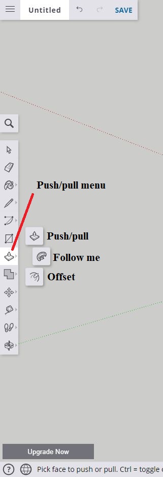
Our push/pull menu gives you three choices, push/pull, follow me, and offset. Today we’re covering push/pull, but we’ll cover the rest in the coming weeks.
Now that you have your push/pull tool selected you’re going to want to switch to a three point view, any one will work, but I selected the bottom right one (shown below in the first image). Now with your push/pull tool selected, click on the filled face of the square we just drew and “pull” up. To do that just drag your cursor up while clicking and holding. Extrude it to 2 inches (50mm) as given in the bottom right dimension window and stop clicking when you get that dimension (shown below in the second image). CONGRATULATIONS! YOU DREW A CUBE!!!


Let’s try that in solidworks. To do that we need to go over to our features tab in the top menu (shown below circled in red). Then we click the extruded boss/base tool
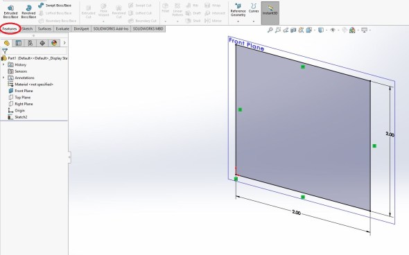
The tabs at the top give us different options, click the features tab * while still in your sketch, do not exit it * Then click the extruded boss/base tool.
It will automatically extrude the shape, but not by the amount we want (probably) so we can type in either 2 inches or 50 millimeters into the menu (left of the screen), you can see what this looks like below.
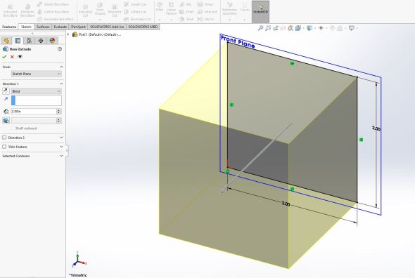
Solidworks gives you a preview of what the extrude will look like. Just enter the correct amount in the dimension box shown in the left menu (by direction 1) and hit enter or click the green check mark.
Once you do that you’ve completed the cube and you now have a cube!! YAY!!! It will look like this guy below.
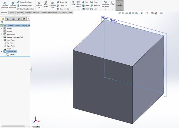
This is our finished cube! Notice our feature tree to the left, we have the boss-extrude and the carrot menu I dropped down shows our sketch associated with it.
Now we’re done! You’ve made your first solid model!! I know it doesn’t seem like much, but things will pick up quickly from here. The main point is that you’re now familiar with how to orient yourself in both sketchup and solidworks. You know some of the camera options and how to move around in a three dimensional space. You’ve seen how to draw shapes and now you can extrude those shapes into fun three dimensional objects!
Save this sketch and give it a name so you can remember what it is, cube would work or even week 3 since that’s where we are. Trust me, we’re going to use this and add to it as we go on. But for now go ahead and play around with some of the other tools I’ve highlighted and see what they do.
If you’re using the 30-Day free trial that is fine, but if you haven’t done that yet, I would wait to do it until we are further along. We may start using tools that we only have access to using the full version, but that won’t be for a while. For the next few weeks AT LEAST we’re using the online (Free) version exclusively. My goal is to make this extremely accessible so no one should have to spend money to do this course.
Since this is a class, there will be homework!
Your homework for next week:
In sketchup draw a circle centered on the origin and in the top view. I didn’t cover how to do this, but I’ve given you enough hints and introduced the tools that you can do this yourself. Give it a 2 inch diameter (50 mm) and extrude it (push/pull it) to 4 inches (100 mm). We’ll be using this as well so you should save it as homework 1 or even cylinder. Sketchup will give you online space to save all these so don’t worry about having it on your desktop.
Good luck, if you have questions feel free to post them and I’ll answer them as soon as I can. In the meantime you can be as adventurous as you want! Sure things might be a little frustrating, but we’ll cover more as we go on and you’ll get the hang of it. In the meantime you drew a cube! Something you didn’t know how to do before, that is a big deal even if it doesn’t seem that impressive.


OOOOOH. I just skimmed over your article, but am exited as I am having issues drawing with Photoshop. Do you need to be a graphic artist, or can a regular shmo like me get around this program?
LikeLiked by 1 person
June 27, 2020 at 1:25 pm
Oh anyone can do it! I have almost zero artistic ability and I can create some really cool looking (and useful) things. I’ll admit there is a learning curve, but once you get into it a little, it’s really easy to do. Like with anything, it just takes a little practice. Most of my writing so far is just to help get people oriented in the software, but once you’re familiar with the tools you can create just about anything.
LikeLiked by 1 person
June 27, 2020 at 1:40 pm
Cool, good to know, I will check it out! I am like a novice stick-figure drawer…I was hoping to transform some of my photos into drawing and photoshop is above my pay grade… 🙂 Thanks!
LikeLike
June 27, 2020 at 1:58 pm