So you want to build a humanoid robot

IT’S ALIVE, ALIVE! Robot paper is live that is and to celebrate this achievement, I’m giving away all my secrets. My poor robot was two long years of work to get right and four years to publish this. But as of this writing, it’s possibly one of the most advanced platforms around, if not the most advanced. That’s a bold claim, so let’s talk about how I did it, why I did it, and what makes it so advanced. This was four years coming, so forgive me in advance for the long post. I’ve REALLY wanted to talk about this.
With all the advancements robots have made over the past four years or so since I built my robot, you would think that my work would’ve become obsolete. I’m arguing that not only is this not the case, I think robot design has stagnated because we’ve overlooked several major problems in favor of the move fast and break things approach. The years long synthesis of my robot hinged (see what I did there?) on a silent war I was waging on the humble, but (in my opinion) evil pin joint. So to understand my robot, we need to understand the problem with the pin.
The pin joint. It’s so ubiquitous we come in contact with one multiple times a day without even realizing it. From door hinges to automotive drivetrains, from motors to computers, the pin joint is everywhere. This is for several reasons (1) pin joints are simple to design, (2) pin joints are cheap to construct, and (3) pin joints are compact enough to be used just about everywhere. Pin joints are great, don’t get me wrong, they are the linchpin of civilization (sorry for all the bad puns). The question most will have is what’s the problem if they are so widely used. So let’s look at the anatomy of a pin joint.
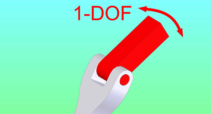

A pin joint is a one degree of freedom (1-DOF) joint. A degree of freedom is a way something can move, but degrees of freedom don’t just mean back and forth type movement, rotation is also a degree of freedom, something to note as we continue our discussion. A pin joint gets its name because there is literally a rod, which we call a pin, holding the two pieces together (above right). You’ll find these almost exclusively holding your doors on, but they are also used for drivetrains and inside your car engine even! Pin joints are cheap and in a lot of cases we don’t need better, so why do better? However, pin joints have a major problem.
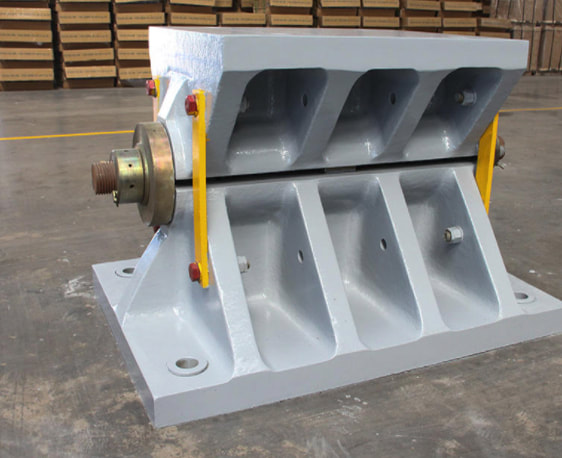
When a pin joint fails, it almost exclusively fails catastrophically. That’s engineering speak for not only does the hinge break, but it takes a lot of things with it. That’s because there’s a single point holding things together so all the force and torque applied to the end of rod gets transferred through that pin. From an engineering standpoint you’re applying a (on occasion) large load to a very tiny surface area, which causes a lot of wear very quickly. Ideally we would apply the load over a large area, which would reduce the wear. Think of this as a nail vs. book. If I apply a force to a nail I can drive it into a piece of wood, that’s because the force is concentrated at the tip of the nail so the force/area is very high. If I apply the same force to a book over a piece of wood nothing happens because the force/area is low (area of a book >> area of a nail head). Even doubling the surface area halfs the force/area, so to compensate when pin joints are used in automotive or other high demand applications they become very long with lots of surface to contact.
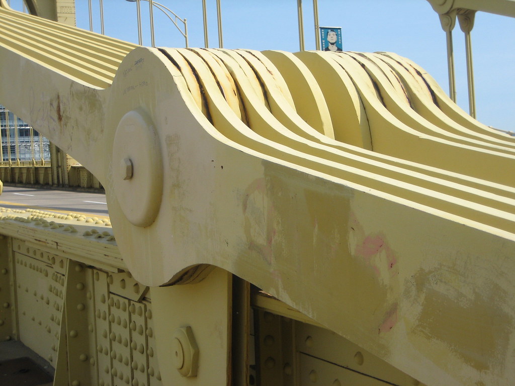
Some of my favorite pin joint uses are in bridges, because they exemplify the problem with a pin joint for high demand, but compact uses, notice how damned wide these guys are (below). Pin joint failure modes (ways of failure) are widely studied and well understood. People have written whole papers on the topic, like this one, or this.

So for robotic uses pin joints do the job they were designed to do and fail spectacularly at them. Which is why in my robot, there are exactly four pin joints and even those are not your typical pin joint. In other words, my robot contains no traditional pin joints, which is the first and arguably the largest advancement I’ve made. To understand how I solved this problem, we’re going to switch gears and talk about the human knee, because the knee is the most complex joint in the body, so I found out the hard way.
The knee is, broadly speaking, a four bar linkage, which alone makes it incredibly complex. Four bar linkages have a changing center of rotation, meaning if I were to squat down, the center of rotation moves from the front of the knee to the back, giving me a longer moment arm. This means when I stand back up, the amount of force my muscles need to generate is much lower than if the joint had a fixed center of rotation. Torque production is force x distance, so if we hold force constant, a longer distance will produce higher torque, if you’ve ever tried to open a heavy door near the hinge you’ve experienced this first hand.
Now there are already a lot of very advanced designs out there that use this four bar linkage mechanism to mimic the knee, but I argue that I’ve done it better for several reasons, one is that the current designs being used are what I call “floating” designs. I’m not sure if that’s an actual term for it, but that’s my term and I’m sticking with it. It simply means that the force is being applied through the pin joints, so once again we’re relying on a pin joint to hold the whole thing together. However, from an engineering standpoint cyclical loading (like what happens when you walk) is THE toughest condition you can put something under (be it heat, force, torque, etc.), it’s just an engineering fact.

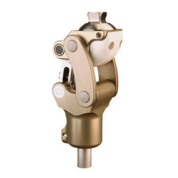
Even if you are not an engineer, you can probably see the issue. The load is applied via the pin joints through through the linkage (the stuff connecting the top of the joint to the bottom). This mimics the knee, but very crudely. Your knee does this better because the two surfaces come in contact, so the load is transferred through the surfaces and not your ligaments (which hold bone to bone). Because the movement of a four bar linkage is so complex, having contacting surfaces is not easy to design (ask me how I know!) My first design, which I’m sharing because you should know engineering is iterative, was a total failure. It was bad, took me months to create and machine, and was a total failure because I attempted to go for the “easy” option and avoid the four bar linkage all together in favor of having good contact surfaces. That paper by the way gets cited a lot as what not to do… oops.

It was back to the drawing board for me. This time I decided to take a crack at designing the best four bar linkage I could. To do this I cheated! No, seriously, I cheated and I am freely admitting it, fuck you originality! I’m not that smart, I can admit that, but neither is nature. However, nature had a few million years of a head start so I stole my design from nature! Using MRI and CT scans, I reconstructed the human knee, hip and ankle. For this post I’ll focus on the knee since we’re already very long.
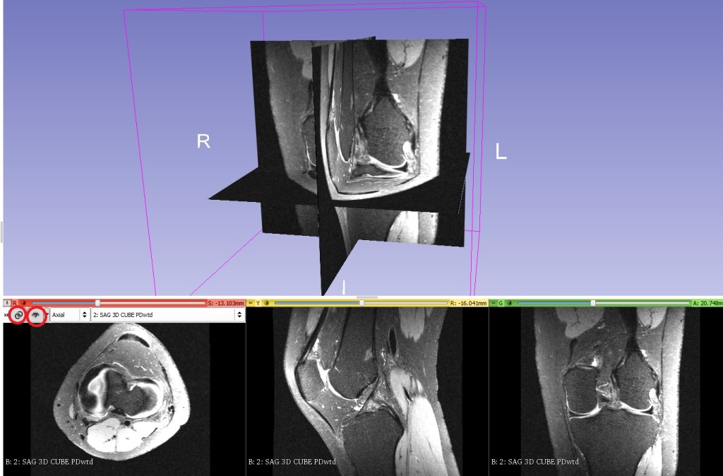
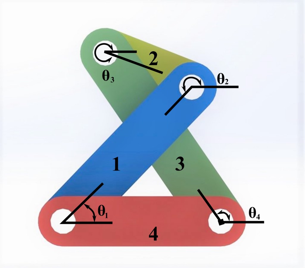
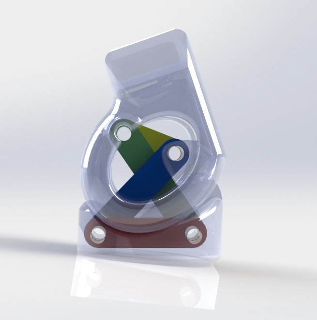
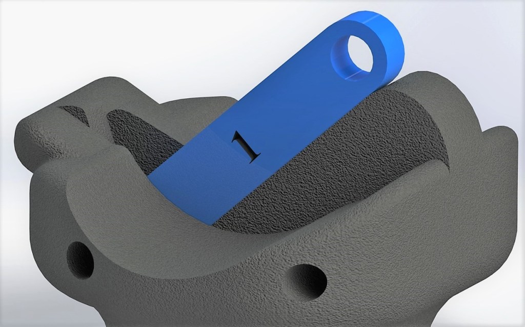
Yep I stole the geometry from the human knee and suddenly everything fell into place. I even made several improvements of my own so let’s talk about how we went from the knee joint, which is a 6-DOF joint to my robot joint (yes, the human knee is 6-DOF, trust me on that or google it). You can already see the 3D model of the linkage I designed above, the four colored links numbered, that’s my design. Or rather the one I stole from nature. From there it was a matter of copying the contacting surfaces and modifying them for better robotic usage (see below).

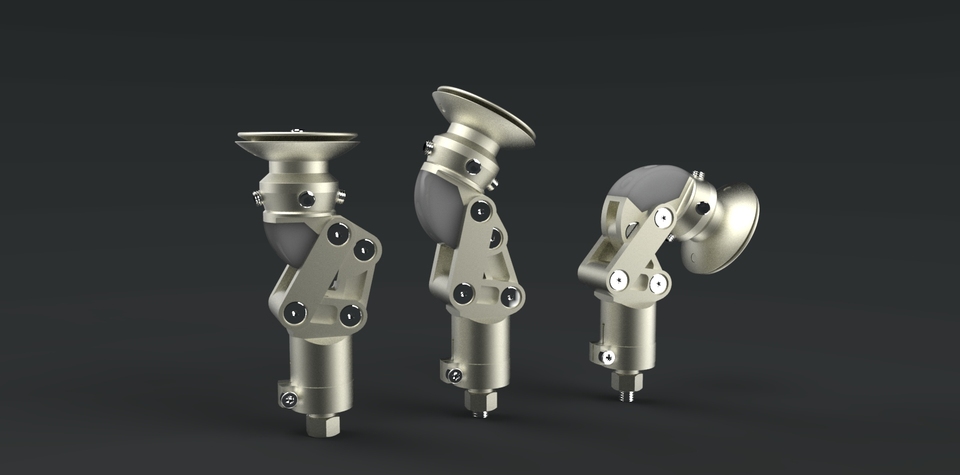
There are several characteristics of the human knee I wanted to mimic. Namely it locks in the upright position. This is energy saving and you’ll hear people tell you not to lock your knees, well we wanted a robot that would lock when standing, so that’s what I designed for. And redesigned, and redesigned. I can’t go through every iteration, but I do keep a lovely photo showing the changes. As a side note, I even managed to increase the connecting bars (prototype photo above left), by almost 100% in the final iteration (this is probably easier to see in the photo above right (notice the thickness), so super tough design.

My knee uses wide contacting surfaces, just like the human knee. This means almost none of the load goes through the pin joint! The pins simply constrain the movement (limit movement), so they see very little loading and when they do, it’s almost exclusively when out of plane forces are applied (meaning forces from the sides).
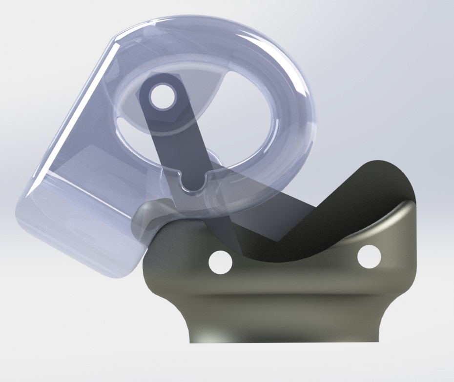
If you wanted to put a direct load on the pins you would need to pull the joint apart (or again push from the sides), but since that almost never happens with the knee in normal use you don’t have the same issue you do with other pin joint designs. This joint will last a very long time and if there is a failure there is very little chance it would be catastrophic. Oh and since I mention locking in the upright position, here’s how I accomplished that (below). When standing the linkage rests on a surface preventing it from moving further forward. The higher the load (the more the robot weighs) the better the locking!
As for the range of motion, it has the full human range! It goes from roughly +1 degree (1 degree forward) to -150 degrees, or 150 degrees backwards, shown below. The center of rotation for a 4-bar linkage is where the two bars cross, notice in my design the two bars cross at the very back of the joint when in the down position like this (squatting). The center of rotation literally cannot be any further back in this design!
So far my creation has the longest moment arm in the down position (again squatting) out of all the knee designs I have come across and I do keep tabs on them because I often wonder if/when someone will design something better. It will happen, but not today suckers! We can plot how the center of rotation changes through the movement. I’ve taken away the x and y axis because the figure was already not that great, but this gives you a good representation of the center of rotation as it goes through the full range of movement.
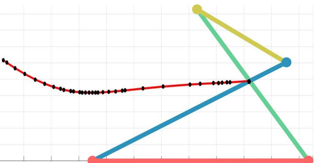
The image above helps see why the blue linkage (shown above where I discuss locking) keeps the knee locked. The joint wants to rotate forward in the upright position and we keep it from doing that by the mechanical stop. There is another measure we use called the sliding to rolling ratio. We want high rolling and low sliding, sliding is like sandpaper, it wears faster, the sliding to rolling ratio in my designed joint is high, which also helps improve the life of the joint. We’re still trying to wear test the design, but so far it’s proven to be very tough.
Okay enough about the knee (I could make several posts about it, but this is already very long! The other joints are much simpler to describe though.
The human body doesn’t use pin joints either, so I wanted to build my robot the way the human body was built. After all, it worked well for the knee, didn’t it? It turns out, the way the nature keeps us held together is by using the most common joint in the body! The synovial joint.

A synovial joint is two contacting surfaces that are held together by a tough fibrous casing. Think of it as two rigid pieces (bones) held together with a sleeve of connective tissue. In fact, that’s exactly how I thought about it and we just happened to have something that reminded me of this in the lab. Air muscles! Festo brand air muscles to be exact, we use them a lot in my old PI’s research because they mimic human muscle so well. They are pneumatically driven (air filled) and as they inflate they contract, so a lot like a human muscle works. I used these for all the rest of the robot joints, from the foot to the 3 piece hip. Yes, I copied the design of the hip so it’s not rigid like most robots. This means it walks more like a human, which is important for the testing we will use it for.
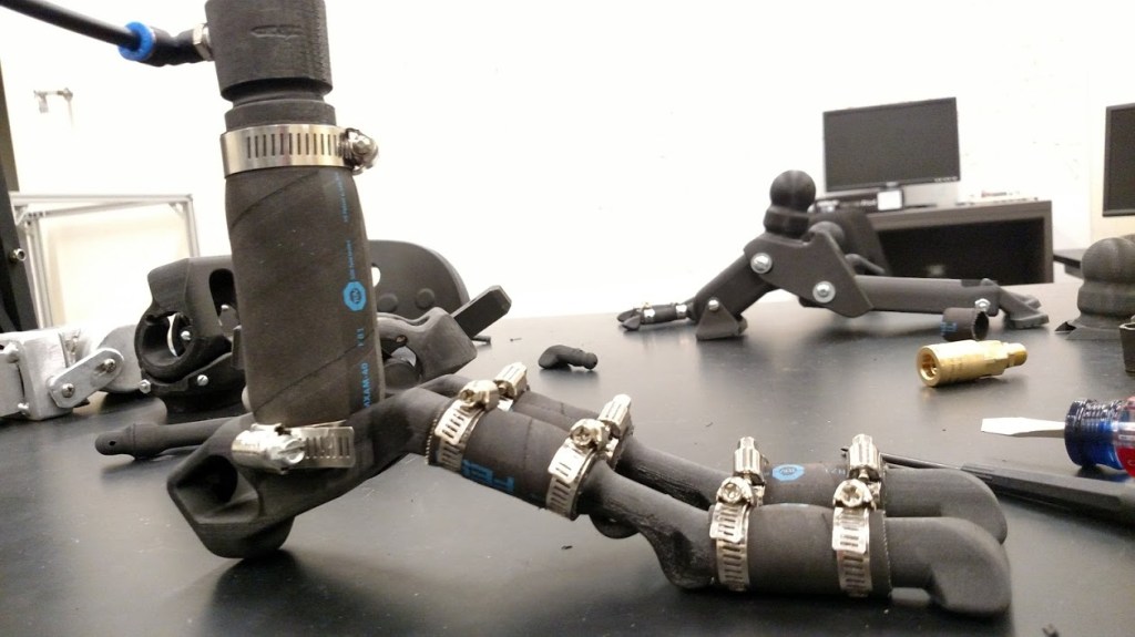
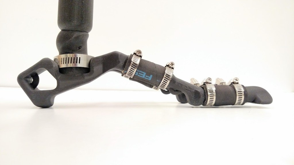

Then came time to assemble the full robot. This was a lot of work and a lot of time.

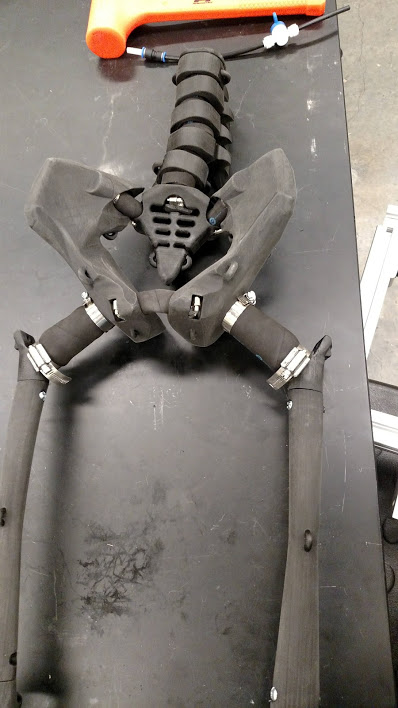

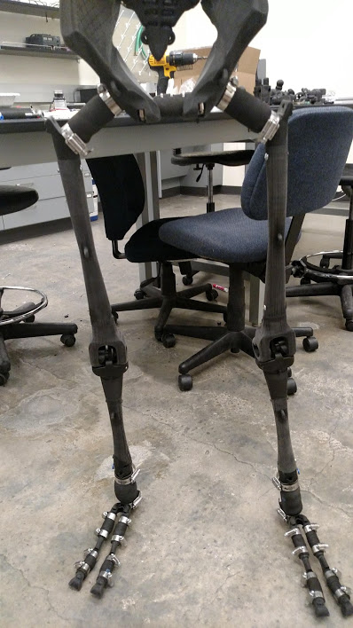
And there you have it. A whole robot, built from CT and MRI scans so that I could be lazy and not have to design it from scratch. I’ve made a lot of changes (two toes for example, because we really only use two sides of our foot), and I’ve “simplified” the knee so there’s no rotation anymore (I moved the rotation to just below the knee, you may be able to see it in the photos above if you look hard enough). But because the joints act very human, we believe it will be easier to control.
It’s semi-self correcting so while the joints are a hybrid type (both soft and rigid) so we cannot tell the EXACT angle, this isn’t a bad thing. Humans are squishy and our robots should be somewhat squishy too. This will help as well with wear because the impact from walking will be damped (absorbed) instead of being forced through a fully rigid robot (think about how crumple zones in cars reduce forces applied to you, the driver/passenger).
Again this was a labor of love and somewhat hate. It’s still a bit sad how this work was received by the community. In the end, I think this was and is still a huge advancement for how robots are designed and how we think about humanoid robotics. I’m proud of the work I did and what it means for the advancement of robotics and in particular prosthetics, this knee will be a huge game changer for prosthetic users.
As a side note, the latest paper is open access, we paid a large sum of money to make that happen because we think this is important work. However, right now it’s in the “early access” stage, which as far as I can tell you need to pay $25 USD to read it. Yes, even me sadly. So while it’s “live” it’s not readily readable as of this post. It should be in the next week or so though, so please have patients if you want a more technical overview of my robot. In the meantime, I have several other conference papers and even my thesis which give an overview of the design. Yes, even my “bad” knee design.
My earlier work isn’t up to the same standard as my latest stuff, but that’s part of the growing process as a researcher, keep that in mind as you read it. It’s good work, it’s just presented a little haphazardly. Luckily this paper I redid some of the figures prior to acceptance so it looks a lot nicer (in my opinion) than some of my earlier works.
Edit!!!!! Robot paper is now live (as in you can read it for free): https://doi.org/10.1115/1.4054441
All the robot sources!!
From oldest to newest:
- First (bad) knee design:
Steele, A.G., Hunt, A., Etoundi, A.C. (2017). Development of a Bio-inspired Knee Joint Mechanism for a Bipedal Robot. Living Machines DOI: https://doi.org/10.1007/978-3-319-63537-8_35
- When I had my idea for a robot synovial joint:
Steele, A.G., Hunt, A.J. (2018). Braided Pneumatic Actuators as a Variable Stiffness Approximation of Synovial Joints. Living Machines DOI: https://doi.org/10.1007/978-3-319-95972-6_48
- A good knee (finally):
Steele, A.G., Hunt, A., Etoundi, A.C. (2018). Biomimetic Knee Design to Improve Joint Torque and Life for Bipedal Robotics. TAROS. DOI: https://doi.org/10.1007/978-3-319-96728-8_8
- My thesis on this work:
Steele,A.G., (2018) Thesis: Biomimetic Design and Construction of a Bipedal Walking Robot
- The whole robot and some added testing of the joints (like range of motion and stiffness):
Steele, A., Etoundi, A. C., and Hunt, A. (2022). “Experimental Verification of Kinematics and Kinetics in a Biomimetic Bipedal Robot.” ASME. J. Mechanisms Robotics. DOI: https://doi.org/10.1115/1.4054441
I believe these are all open access, if not there should be copies floating around somewhere, google scholar lists them all as open access for example. If you want to read anything and it isn’t feel free to find me on researchgate and I can send you a copy.


This looks so neat. Congratulations on getting it out there for everybody to see. It does my heart good to watch you enjoy talking about it.
I’m a little surprised you didn’t get more respect for the biomimetic approach. Not only does it make a lot of sense to follow a design that already exists in nature and works, but also – for prosthetics specifically – I would expect people to be most comfortable with a device that resembles the natural knee they’re supposed to have.
And no, I was not expecting knees to be that complicated. I don’t think I had even thought of ligaments as linkages, per se. I knew they were necessary to keeping our joints interlocked, but I wasn’t fully aware of the role they played in constraining the motion.
I may have laughed a bit too much at “my robot has cankles.”
I’m developing a small pile of questions, but maybe I should wait until the paper emerges from early access, and see if they’re answered there. I did take a look at your thesis, but it appears I can’t read more than the first few pages without the right institutional affiliations (and my public library doesn’t cut it).
LikeLiked by 1 person
April 28, 2022 at 2:46 am
Thank you! I’m so happy I finally got to this point, it felt like it would never come. Especially as the years went by.
I felt the same way, I’ve gotten several complementary reviewers, who all agreed the knee was a paper all on its own, but for some reason the whole robot just didn’t cut it or something. I’m not sure what the issue was, probably because it’s not “finalized” and walking on its own yet.
When I started I thought the knee would be the most simple joint so I built up from that. In a way it was good that I started there because the knee took by far the longest amount of time to figure out. Machining the aluminum one in particular was such a pain. I have horror stories from that, one about a tungsten tap that broke as a I was creating threads. That was a mess.
I’ll probably make one more post once the actual paper goes open access, so you won’t miss it.Supposedly I will get an email letting me know. It’s a little frustrating that we paid the money for open access, but it’s still paywalled for the first week(s) of it going online.
Apparently the google scholar reference I used wasn’t the open access version. I’ve fixed it since my thesis is open access, but here’s the updated link: https://pdxscholar.library.pdx.edu/cgi/viewcontent.cgi?article=5557&context=open_access_etds
Let me know if that doesn’t work either. Who knew sharing my work would be so hard. lol
LikeLiked by 1 person
April 28, 2022 at 1:53 pm