Day 320: Solid Modeling – Week 4

We’re making something a little more exciting than a cube today. Yay!
Welcome to week four! For those of us just tuning in, this is a class for solid modeling using FREE software, so if you have internet access, you can do this too! You can find the whole course in the handy Solid Modeling for Beginners category. Last week we introduced a whole lot of navigation tools and helped you get situated into the world that you’ll be able to model in. So let’s get started by doing a quick recap of the past weeks and hopefully you’ve done your homework because we’re using that part today to make something more impressive than a cube.
First if you’re just joining us you’re going to want to get the software side figured out. We are using two different programs technically, you’ll be using the free version of sketchup. It’s totally online based so you don’t have to worry about computer requirements you just need internet access. Or you can download the 30 day trial if you want, but I would wait until I get into the details of the paid version of the software.
I’m also using Solidworks, since my class is a Solidworks course specifically and these are good notes for my students. This is expensive software, so if you don’t have access it’s okay, I’ll be doing the same exact thing in both modeling software so you can see that they are basically the same thing, most of the differences are placement of the tools. So now on with the recap.
Okay I think bullets would be the cleanest way to do this so let’s go:
- Week one: I showed you that the most complex objects can be thought of as simpler shapes that make up that object. I did this by taking a seemingly complex shape (a cat toy) and modeling it using this principle. That was the first time I attempted to model that toy, so you got the chance to see my thought process as I did it. The take away being look at objects as simple shapes and you’ll be able to model the most complex looking things easily. (with the exception of forks, the solid modeler kryptonite)
- Week two: This week we revisited the cat toy, this time instead of making it in several steps, I did it in a single step, the whole thing in just one sketch. Then I explained why this is a horrible idea and that you shouldn’t do this. While you could do this if your part is throw away or practice, it isn’t a good idea in general.
- Week three: We finally did it. We got into the gritty world of solid modeling using the free software sketchup. I spent a considerable amount of time introducing some basic tools and more importantly I showed you how to navigate in this pseudo-three dimensional world. I ended the post by showing you how to make a cube and then I gave some homework, which we will use today to make something a little more complex.
Each week we will be building on the previous weeks so it’s a good idea if you’re just joining to start at the beginning unless you have experience already. These posts get really long and I apologize, but I want to make sure I cover all the steps so you aren’t left scratching your head about how I did something
Hint: if you ever do scratch your head or want clarification, just leave a comment and I promise I’ll answer as soon as I can.
For week four we are going to start by opening your homework I gave you. You were tasked using the things you learned last week to create a cylinder with a radius of 2 inches (or 50 mm) and a height of 4 inches (or 100 mm). So when you open that you should see something like this (both versions of software shown below).


Okay so let’s get started and make something more interesting than a cylinder or a cube shall we? Here’s where we go with the overly honest methods section, I’m still not sure what I want to make with this cylinder, I have an idea though so we’re going to do that as I’m writing this so if I mess up, we can correct it and you’ll see how I fix problems I’ve made for myself. I’m not going to give away what we’re making yet, but it will be fairly simple since we’re just starting out. This is only week four after all!
First, my idea means we need to change some dimensions. Right now, we have a cylinder that is 2 inches in diameter (50 mm) by 4 inches (100 mm) let’s make that a 2 inch (50 mm) by 12 inch (let’s say 300 mm even though that isn’t exactly the conversion for any of this, but we’re making something for fun so we don’t really need exact measurements for this). Let’s do this in sketchup first. To do this you’ll want to click the top face of the cylinder. I would switch to a three point view (like you see above for the sketchup software), then click the top face. It should look like what’s seen below.

Notice the top face is highlighted with blue dots
Now select the Push/pull tool, you should be familiar with this by now since we used it last class. Then click and drag the top surface and you’ll find that we can lengthen it! Notice the measurements window at the bottom right of your window, it starts at zero again so we need to remember that if we want a 12 inch (300 mm) long cylinder, we need to only add 8 inches (200 mm).
To do this is Solidworks, we can simply edit the extrude we did and change the dimension from 4 inches to 12 inches and it will adjust accordingly. Use the feature tree on the left, right click on the boss-extrude step in the tree (it should say something like Boss-Extrude1) then change the value from 4 to 12. You can see the change in the images below.


Okay so now we have our cylinder to our dimensions we want. Let’s do something a little new. We’re going to freehand a shape using the line tool (not the freehand tool, there is a difference). We covered the line tool in the last lecture, but for completeness, let’s take a look where that tool lives in both solidworks and sketchup.


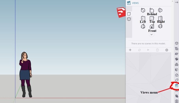
Now as I’ve discussed drawing in 3D space without looking directly at the plane you are working in is a perilous endeavor! So in both solidworks and sketchup we’re going to change to our front view. To do that in Sketchup you’ll want to go to the views menu on the right side of the window and select the front view. In Solidworks hold the shift key and press the 1 and it will move you to this view automatically. Again, we covered where this tool is in the last lecture, but for completeness here it is again for sketchup (since solidworks you can do this via quick key).
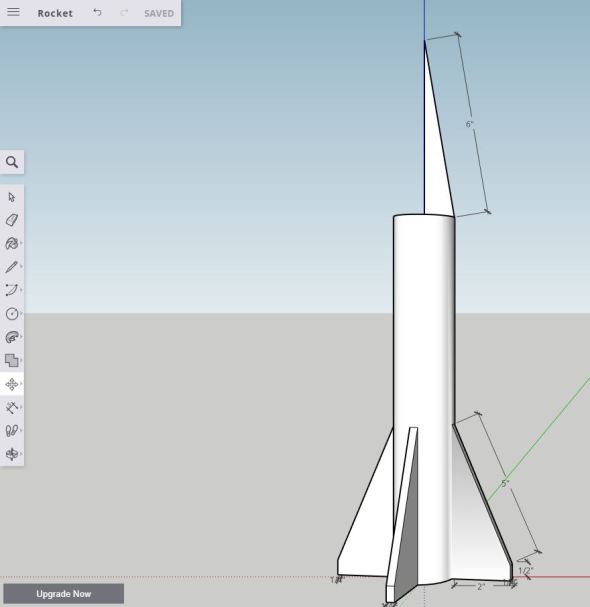
Now that we are in the front plane let’s draw. I’m going to spoil what we’re making here, but you’ll know what it is as soon as we draw this part, so let’s just get to drawing the part. You’ll want to start at the base of the object if you’re using sketchup and make a two inch line, parallel to the red axis (you should see a red line and a little note letting you know that you are working on this axis in sketchup) Start it at the base of the cylinder, it will pop up a window saying endpoint, click there and drag it out two inches (50mm) (using the length menu at the bottom right). Then go up 1/2 inch (13 mm) and finally we’re going to draw at an angle a 5 inch (125 mm) line to the cylinder. Again when you meet the cylinder a window will popup letting you know where you’re adding the line, make sure it says endpoint and not on edge. Lastly you’re going to want to close the sketch by drawing a line from the top line to the bottom line (the only place we haven’t drawn a line, it should snap to these points, make sure you’re snapping correctly though). It’s easier to see this in picture form so if you’re scratching your head now, see the image below.

You should have something like this and it should be filled just like this when you’re done. If not I would start again and make sure you drew the bottom (2 inch or 50mm line) starting at the cylinder and the popup window says “endpoint” and NOT “on edge”
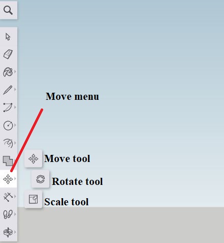
I went ahead and added dimensions to this so you could see what it looks like. Frustratingly, sketchup doesn’t let you adjust the part by the dimensions, solidworks does. You can drag and resize using the move and scale tools should you need to do any of that. We haven’t covered that or how to dimension your part so before we jump into the solidworks version I’ll show that really quickly. The move menu can be found in the left toolbar and is the four arrows (shown below) in this menu lives the move tool, the rotate tool, and the scale tool. I would suggest you play with these tools, but in this case since we are drawing a line, the move tool would be your best tool for this job, just click the end of the line and you should have a dot appear that will let you drag and resize your part. It will also let you snap the line to the cylinder if you missed it the first time. The scale tool here would resize in weird ways (mostly) specifically if you tried it with the angled line (the 5 inch or 125 mm line). Try it, you can always undo anything with the ctrl+z command (in windows) or at the top by the name of the part the arrow pointing backwards since I’m not familiar with mac.
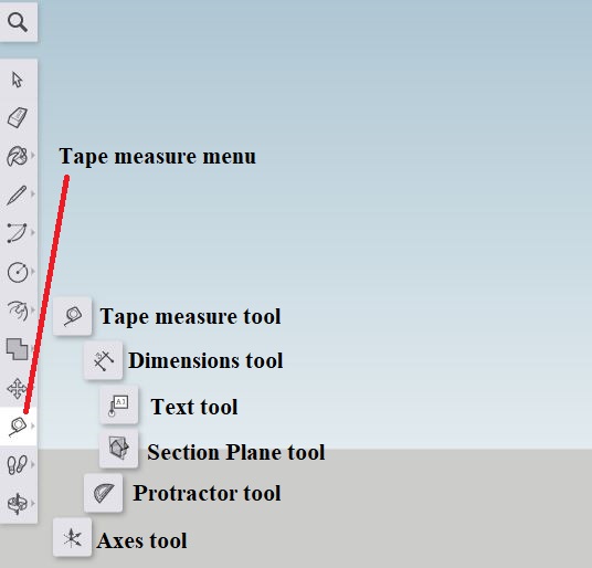
To add dimensions we have right below that the tape measure menu. We’ll cover all the tools in this menu eventually, but let’s go over the two you’ll most likely use the most. That would be the tape measure and what I just used the dimensions tool. Both let you measure parts, the dimensions tool places the measurement like you saw in the image of the fin I just drew. The tape measure literally just tells you what the measurement is between two points, you click the two points and it gives you the distance between the two. In this case if I did it with the line, I could adjust the size by entering it right after (it would appear in the length menu in the bottom right. The dimensions tool gives you the dimensions of the part. Be warned, you can edit these dimensions, but it will NOT change the dimensions of the actual part.
What’s nice about the dimensions tool is that if I use the move tool, the dimension will automatically update as I drag the end of the line so if you’ve got the wrong dimensions, you can adjust it without having to look to the bottom right of the screen. With sketchup drawing this is going to be hard, so I would suggest if you are having issues to change the views regularly. For example I drew the bottom line (the 2 inch or 50 mm line) in the bottom plane, the 1/2 inch or 13 mm line I drew in the front plane, and the 5 inch or 125 mm line I drew in the side view (looking directly at the line I was drawing so all I saw was the line), then I adjusted my line sizes using the move tool.
In solidworks this is a much simpler operation. We can draw our entire part in plane without worrying about drawing out of plane. To do this, create a sketch in the front plane (right click the front plane and select the sketch option at the top left of the popup menu). Select the line tool and we can rough out the lines. Just like sketchup, we’ll have to close this sketch, and it will be easier to see what that means than it was in the last image. To do this, we’re going to need to add the line at the cylinder, you’ll see what I mean in a moment. After you have the rough shape you can use the smart dimension tool to correctly size the lines
Now let’s look at the next step in solidworks first then we can go to sketchup. In solidworks WHILE WE ARE IN THE SKETCH click the features tab at the top of the window. Select boss-extrude and we are going to make this 0.25 inches thick (13mm) and for direction we are going to select midplane. See the image below, direction 1 has a dropdown menu that will let you select this option and the D1 menu will let you set the correct dimensions. Also make sure that the merge result box is checked since we want one solid part (see below).
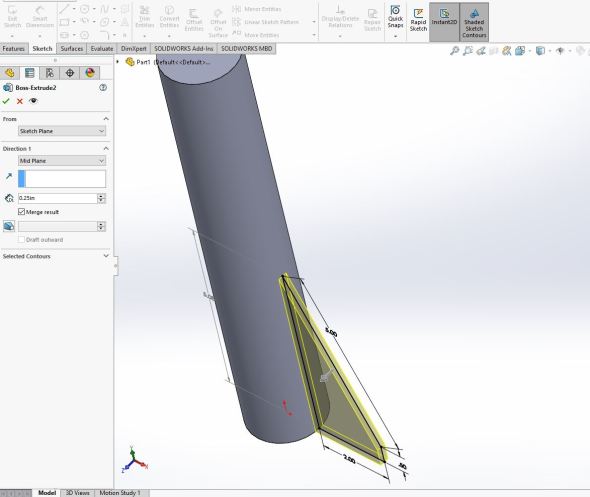
Notice the menu to the left, I have direction 1 set to mid plane and the D1 is 0.25inches or 13 mm. The merge result box is checked, then click the green check mark right next to the name Boss-Extrude 2
Now for some fun in sketchup. Sketchup is a little less friendly in this case, at least the free version isn’t as friendly. Let’s take a peek. In sketchup we need to extrude in two directions independently, unfortunately the free version won’t let us merge the parts like I want, you can only do it in the paid version. If you want to see why that is a problem go ahead and try extruding the face of your fin yourself and look at how it connects to the cylinder, it doesn’t. Never fear! We have a work around! We will do something slightly different and use the follow me tool. This will be slightly more difficult, but hey we’re using the free version for a reason, so we do the extra work. Now we already covered the follow me tool, but here is where you can find it.
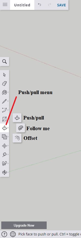
The follow me tool is in the push/pull menu and is particularly useful in this case when we bump up against the limitations of the free version.
To make sure our part is connected to our round cylinder, we are going to use the follow me tool (select it) then click on the face of our fin. Before you do that keep reading so you know what’s going to happen next. You’re going to use the bottom circle of the cylinder to guide the follow me tool (it will turn red) and drag it, mine snaps to an endpoint and I accept that since the tool is hard to use. My fin is 1/4 inch thick now and yours should be about the same. Unfortunately it’s now off our plane. It’s okay we can fix that if we need to.


So now we have our fin, in solidworks the next step is super easy! So we’ll go with that first then we will do the equivalent in the free version of sketchup, which means slightly more work, but doable!
In solidworks you’re going to want to go to the features tab at the top of the screen and find the linear pattern tool, next click the carrot to bring out the dropdown menu (see below).

You want to select the circular pattern tool (highlighted above). This will bring up a somewhat complicated menu, don’t worry I know it’s overwhelming, but it’s not that hard to use. First we need to select Direction 1, that will be the bottom edge of our cylinder. Next select equal spacing, since we want them spaced equally apart. The next menu in this list gives you the degrees, since we selected equal spacing, it’s set to 365 or one full circle. The next menu is our instances menu, or how many repeats we want. Since we’re building a rocket (spoiler) we will select 4 repeats, you can do 3 or even 2 if you want, it’s your rocket, there’s no rocket shaming here.
Ignore the direction 2 menu, we don’t need it and it should be unchecked by default. Next we have the features and faces menu. Ignore this menu as well and unclick it. Instead we want the next menu, the bodies menu. Make sure the bodies menu is checked, then click inside the white box in that menu. We’re going to select our fin that we just extruded, it should call it by name as boss-extrude2 or something similar. Make sure you are in this little box or it will try to replace the direction 1 feature you selected. You should see something similar to what I have below (I selected 4 fins because I like the look of it).
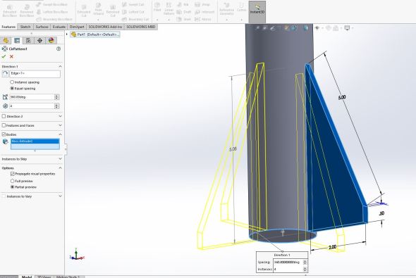
The image above shows the menu options I have selected on the left. If you prefer a visual guide, just go through the left menu and make sure you’re set the same way (with the number of fins you want for your rocket). When you like the way it looks click the green check mark at the top of the menu at the left (by the name of the operation, in this case CirPattern1).
Unfortunately the free version of sketchup isn’t as kind. We’re going to have to manually draw each of these fins so now is a good time to believe less is more if you don’t want to put the effort in. However, if you do then let’s get to work! I like my four fins and I don’t mind having to do the work to get it, since the follow me tool will offset the part reliably (at least that’s my understanding) we can draw the other fins in the corresponding planes and they will automatically be equally spaced. So I’m going to skip over a lot of this since it’s the same step as the first fin repeated four times. However, I will give you a hint, use the views menu to select the different planes (so right side, left side and backside, or you can use just two different planes if you want to be ambidextrous like that. With all that out of the way, I’ll jump to showing you the three other drawings of the fins in the different plans (seen below). Once you’ve done one, the rest are pretty easy so you shouldn’t have too much trouble with it.

Note two things, one fin is blue, that signifies I’m looking at the back of the sketch, second I didn’t dimension any of the new fins. I didn’t need to dimension the first, it was more for you than me, but sketchup will snap to some of the fin dimensions (namely the 1/2 inch or 13 mm line). I like drawing the long angled line looking directly on the sketch so it looks like a straight up and down line, that seems to be the easiest for me, but you may find a better way to do it for you.
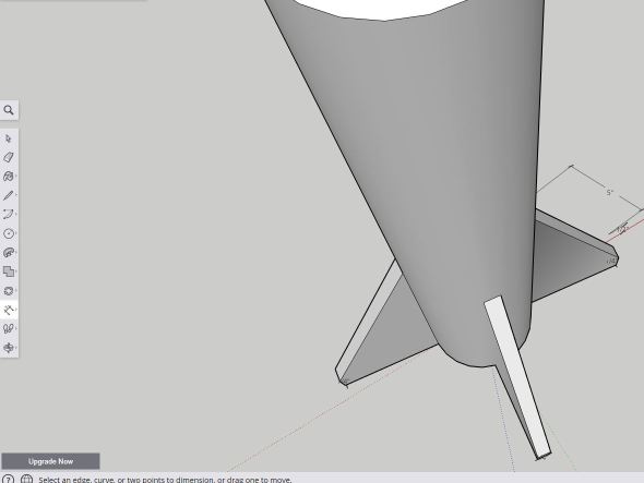
Okay so now we have our fins and we’re going to follow the same operation we did to extrude the first one. Again since this is just a repeat of the follow me step, I’m going to just jump to the finished product after I used the follow me tool to extrude the other three fins. REMEMBER: To ensure your fins are nicely spaced (see: normally spaced) you’re going to want to use the follow me tool in the same direction for all four fins (if you’re doing four). Or you’ll end up with weirdly spaced fins. If that’s what you want, go for it I’m not here to fin shame, but if you want it to be evenly spaced, you’ll want to go the same direction for each. Below you’ll see what I ended up with. It snaps at every ~ 1/8 of an inch or ~3 mm so I ended up with one fin that was 1/8 inch, I just went back and fixed it so I had 1/4 inch (~6 mm) fins all around. Below is an image showing three of the four fins (it was difficult to get all four to show nicely).
Note I keep using extrude to describe what we just did and that is technically correct, but the tool we used to do that is called the follow me tool in sketchup, a little weird if you ask me, but I’m in no place to judge.
Okay we are almost done with our rocket, let’s go ahead and add the final touch which is the nose cone. To do that we’re going to create a right triangle at the top of our rocket, then use the follow me tool to close it 365 degrees around the top. Let’s take it step by step. We’ll use sketchup first, then we can jump to solidworks. First I used the top plane view and the line tool, it will snap to the center of the circle draw a point there and drag it to the edge of the circle and place your next point there along one of the main axes (you’ll see why in a minute). Then I switched to the front view (or whichever view lets you see the drawing best and drew a line at the axis that runs down the center of our rocket (this is why we drew it centered to this axis way back in the first step I gave you for your homework). Then I just closed the sketch and it automatically fills in the sketch. It will snap to the point so you should not have any trouble closing the sketch. If you do, no worries just undo and try again or you can use the move tool and place it until it snaps. Next, I used my dimension tool, since I like doing that, and I dimensioned the hypotenuse (if you’re not a big math person see below). I used the move tool to drag it to be 6 inches or 150 mm long since I like a long nose cone. Just like with your fins, if you want a different style or shape for your nose cone, I won’t nose cone shame you.
Now we will use our lovely follow me tool to revolve this sketch and create our cone. To do that select the follow me tool, I would switch to a three point perspective for this, then use the circle of the cylinder to revolve the shape 365 degrees until you end up with a completely closed nose cone like the one I have below.

To do this in solidworks, it’s not too different. We’ll create a sketch in our front plane again and draw the same shape like we did in sketchup (see below). The difference is the tool we will use to revolve this. It’s actually called the revolved boss/base tool and that’s how I know it so I always refer to this operation as a revolve (just fyi). Once you create a sketch I would start by drawing the base of the triangle, to do that you’ll be able to snap to the center of the cylinder, draw a line starting from the center to the end, again it will snap then draw the 6 inch (150 mm) line by going close to the center and then moving your mouse up, you should see a dashed line letting you know that you’re parallel to that point, place your point and close the triangle Dimension the hypotenuse so it is 6 inches (150mm). You should have something like you see below.

Staying in the sketch, we can click the features tab (top left of the screenshot), then we will select the Revolved boss/base tool (second tool from the left). It will ask for a axis of revolution (if it doesn’t automatically select it), pick the line the center of our cylinder and it should revolve 365 degrees automatically (shown below).

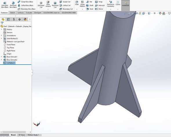
As usual, click the green checkmark by the name (Revolve) and you’ll have a simple rocket! Now, I did a little extra and then threw some color on it (I was feeling like some Iron Man colors today), but it’s still the same thing we just did here. You can add extra fins, or play around with other options, maybe you don’t want a nose cone that shape, maybe you want a fun rocket shape instead of a boring cylinder, do it! You now have the knowledge to make it happen! That said, today we’ve made something slightly more fancy than a cube or a cylinder. This was a long post, but I hope the payout was slightly more worth it than the last one.
I also just realized that in America we celebrate fourth of July as a holiday. I’m not a fan! But you may get the impression that this was some odd patriotic attempt. It’s not, I just have a deep love of space and space related things! For that reason, I thought a rocket would be a fun way to use the cylinder we made last week.
Homework for the week: I want you to create a sphere using the follow me tool, make sure it has a radius of 2 inches (50mm) and centered about the origin. You’re going to find it always helps to be centered at the origin when you’re making parts. What will we do with it? Well I’m hoping to have that figured out next time we meet!


But enough about us, what about you?