Day 327: Solid Modeling – Week 5

Okay everyone, I had a bright idea for our sphere… get it, get it!?!
Wow, week five already! As per my usual intro, this is a free class using FREE software so if you ever wanted to create a 3D model, this is for you and all you need is internet access to use the program we will be using. Now if you are just joining you’re going to want to start at week one, which you can find all the posts in the super lovely Solid Modeling for Beginners category. We finally did it, last week we made something cool looking! Today we’re going to expand on that and use what we learned to create another awesome thing!
I liked how I did last weeks post, so let’s do a bit of a recap and a reminder, we are using two different programs in this course. These notes are for my solid modeling class, which is using SolidWorks. SolidWorks is not free and most people don’t have access to it, so to make this course as accessible as possible we’re also using the the free version of sketchup.
Now I’m probably doing let’s say ten weeks of these lectures, maybe 12, we’ll see, so you can download a 30 day free trial of sketchup which has more functionality, but I suggest you wait until we dive into that and I’ll warn you the features I’m covering are in the trial/paid version before I use them so there will be no confusion. That said, let’s get a shorter recap than I did last week, these posts are getting far too long!
- Week one: I showed you that the most complex objects can be thought of as simpler shapes that make up that object. I did this by taking a seemingly complex shape (a cat toy) and modeling it using this principle.
- Week two: This week we revisited the cat toy, this time instead of making it in several steps, I did it in a single step, the whole thing in just one sketch. Then I explained why this is a horrible idea and that you shouldn’t do this.
- Week three: We finally did it. We got into the gritty world of solid modeling using the free software sketchup. I spent a considerable amount of time introducing some basic tools and more importantly I showed you how to navigate in this pseudo-three dimensional world. I ended the post by showing you how to make a cube and then I gave some homework, which we will use today to make something a little more complex.
- Week four: We made a thing! A rocket to be exact and you had more homework so today we’re using the sphere we made.
As usual I do my best to explain things I think may be hard to follow along with as I jump back and forth between SolidWorks and Sketchup. However, I have experience using solid modeling software so what I think is easy may not be for you. That’s fine and if you ever are confused feel free to drop a comment and I’ll clarify as best as I can or I’ll break out a new post so I can go into detail about something I missed. My goal is literally to help you learn and if you need help, just ask!
Okay so last week we said to create a sphere with a radius of 2 inches or 50mm for you metric people out there. Since we should be used to the tool placement in both Sketchup and Solidworks, I won’t be covering where these tools are unless I use something I haven’t covered already (I’ll try to link to the posts where the information is located to make it easier on you). Now as with my previous posts, I’m doing this for the first time alongside writing this, this way you can see my thought process and if something gets messed up, how I try to fix it. You can also see how I work around the limitations in the free version of sketchup (like last week with the rocket fins).
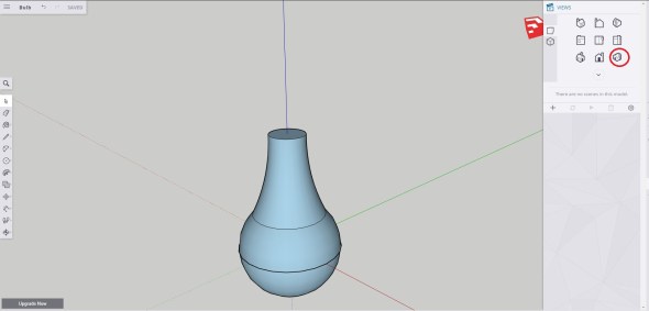
That said, let’s open our part. Below you’ll see my 2 inch (50mm) radius sphere in both SolidWorks and Sketchup. I did say radius, so the diameter is 4 inches or ~100mm. Fair warning, I didn’t get to the end of the design today, but don’t worry we have plenty of time, I’m not going anywhere.


This is also where I should probably apologize to the sketchup folks. In Solidworks making a sphere is easy since we can use the revolve tool and revolve around an axis (you can see the dotted blue line cutting into my sphere in the shot above. In sketchup you need to draw a second sphere to guide the “follow me” tool (you can see the line of my second circle cutting in the center of my sphere above). So I’ll take a step back for just one second and walk you through sphere making in sketchup, in case you had any confusion for last week’s homework.
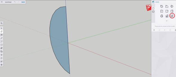
If you’re using solidworks or don’t want to learn this part, you can skip ahead. For everyone else, let’s get started. So what you want do first is create a half circle, this is actually pretty easy, we create a whole circle at the origin and then cut it using a tool I haven’t introduced yet, the eraser tool. First create a 2 inch (50mm) radius circle centered at the origin, the tool will snap and say origin, so you know you’re on the right spot.
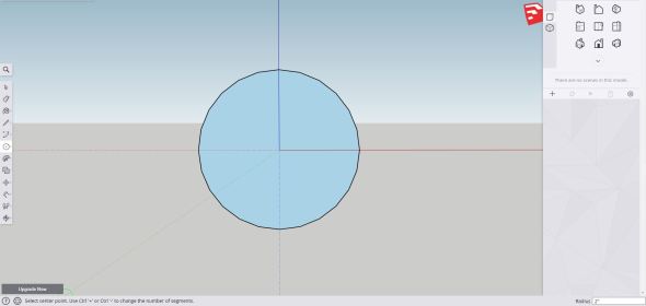
Notice the radius is 2 inches and I’m centered about the origin. I used the front view to make this.
Now we get a bit more complicated we’re going to use our line tool (which we covered last week) to draw a line that bisects our circle. In other words the line cuts it in half. Since we are centered about the origin the tool will “snap” to the blue axis (in my frame of view anyway) and the outer edge of the circle, then the end point will be the bottom of the circle and you should have something like what’s seen below.
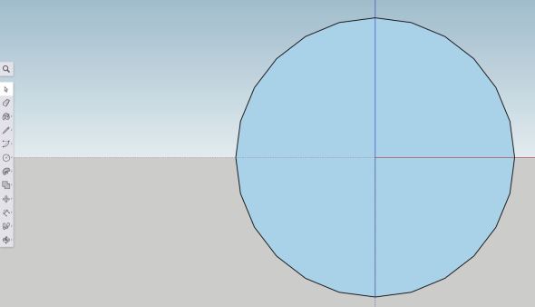
It’s hard to see and I apologize for that, but the line cuts right through the circle along the axis (notice the difference between this image and the one above, the line is solid through the center).
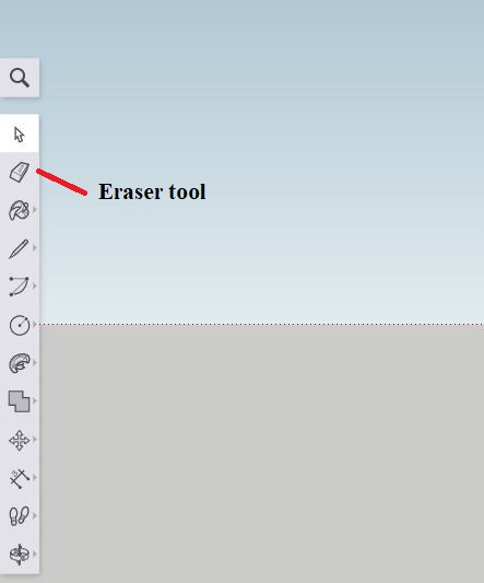
Now we can introduce our new tool, the eraser tool. This guy is located without a pop out menu so we only have the single tool. It’s the one that looks like an eraser, but for completeness sake, you can see it pointed out below.
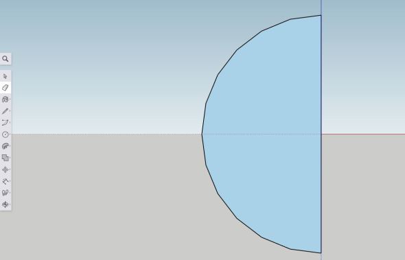
Now we (probably) don’t have to do this, but old habits and I use this method all the time in solidworks to make my spheres, so we’re using the same technique here. It’s good practice since most solid modeling software will get mad at you for using a whole circle, you can try it if you’re feeling adventurous, but alas I am not right now. So click the tool over half of the circle and it will erase the outer edge and the inner blue area up to the line we just drew. You should see something like what’s shown below if you did it correctly (if not, you can always undo and try again!).
Now if we tried to use the follow me tool, it wouldn’t do anything! Trust me I tried!
Okay so now we need to make the path for the follow me tool to do its thing. To do that we’re going to switch to the top view(ish) see I like having my second circle centered at the origin, but if you work from the top view chances are you’ll draw it on the top of the circle. This is completely a preference thing, but also it is just cleaner to have it incorporated in the center of the half circle, so we’re going to use a three point top view shown below (I circled the view I clicked to get here in red).
Now for the semi-tricky part. We want to create a circle on the green/red plane. To do this we select the circle tool again and hover over the origin. You should see a pop up that says center and the circle tool icon on your cursor should change to show you which plane you are adding the circle, it should look like what we see below.
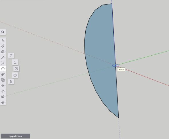
Notice it says center and has the circle icon clearly in the red/green plane. You’ll want to move the cursor around until you’re in that plane too.
Now draw your circle with a radius of 2 inches again (50mm). If you stayed in the plane you should have a half circle with a full circle cutting through it. May certain your radius is set correctly or you’ll have to fix it afterwards. If you’re confused, you should end up with something that looks like the image below.
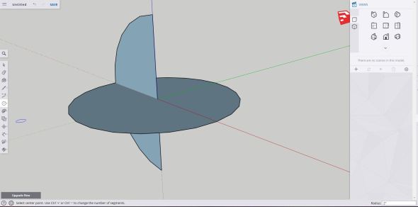
Notice my radius is 2 inches (50mm)
Now we can use the follow me tool, click on the face of the half circle and use the outer edge of the circle we just drew (the full one) to create the sphere, you may need to rotate your view while you do this, but if you follow around the circle and click on the edge where the full circle and half circle meet, you should get a fully closed sphere, like the one seen below!
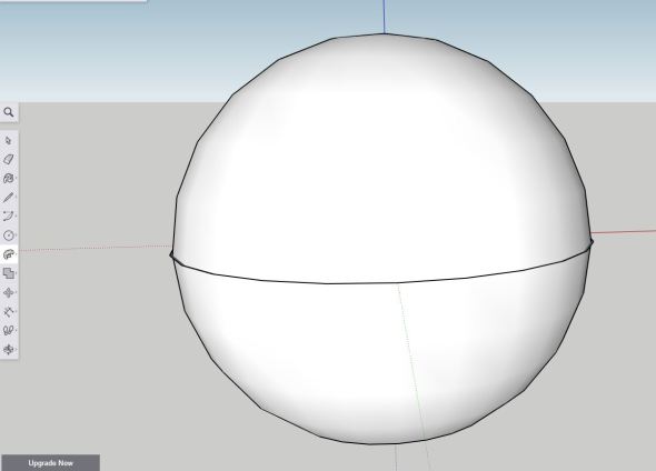
Technically we could delete the circle we just used to make this sphere (the full circle that cuts through the center of the sphere), this would give us a full sphere with no lines at all, just a sphere floating in space basically. I had a note here saying you could delete yours (Hey I remembered!) don’t do it, we’ll use that circle again later so leave it for now.
Okay, moving on, so now everyone has their spheres… I hope. Unlike last week, I had a bright idea and figured out in advance what we’re doing with this sphere. Let’s get started and in the end we’ll have a nice little… well you’ll see (note: I probably set the finished product as the header image so I don’t know why I try to pretend like it’s a surprise). Sorry for the side track, back on course. Next let’s revolve an odd shape around, you’ll see what I mean in a moment. Up to this point we’ve only drawn straight lines or predefined shapes. Today we’re going to draw a curve or in sketchup an arc. I don’t think I covered that tool yet so in sketchup we find that tool in the menu below.
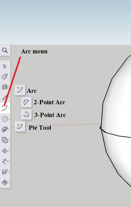
Welcome to the arc menu! Here you can find several ways to draw arcs, you can also have some pie. It’s tasty. Oh, not that kind of pie, the pie tool draws a 3 point arc, but in a pie shape *Sad no pie face*
Today we’re getting a little abstract unfortunately, so this will be more on your artistic opinion rather than me giving you precise measurements, but hey that’s half the fun of learning! Okay so we know where the tool is in sketchup, in SolidWorks we have an arc tool, but we are using the spline tool instead, again we’re bumping up against the limitations of the free sketchup, but no worries! So here’s the location of the spline tool in Solidworks. You’ll go to sketch, select the front plane and create a new sketch in the front plane. You’ll automatically get sent to the sketch toolbar tab (assuming you didn’t use it to create the sketch), the spine tool is the one that I’ve circled and here’s the little information bubble that shows up if you hover over it for a moment.
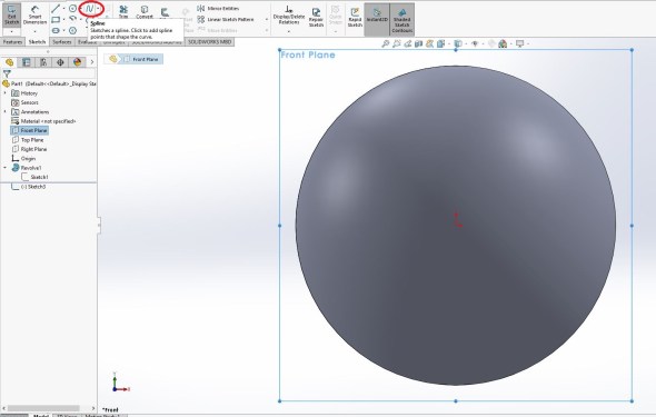
The spline tool is different from the arc tool in that it doesn’t force you to draw a circular arc, you can create weird wavy lines and other things. Since sketchup doesn’t have one, we aren’t doing anything super crazy with it, but it’s easier to use for our purpose than the arc tool.
Since I’ve spent the bulk of the time in Sketchup, let’s do this next step in Solidworks first then we can swap back over to sketchup and repeat it using the tools we have available in the free version.
For the Solidworks group, here’s what we do. You’re going to create a line at the center of the sphere and make it vertical, length isn’t a big deal (shown below). Next set it to for construction in the menu when you select it (shown below circled in red). We’re going to revolve this shape, so we want to have a center to revolve around.
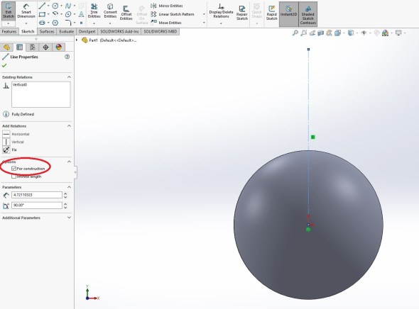
A for construction line means solidworks will ignore it when we want to extrude or do anything using the sketch unless we select it specifically for a axis of rotation or something similar.
Next we can use our spline tool. If this is your first time using the tool we’re going to take it in baby steps, if it isn’t then you should be able to move ahead some. Draw a straight line from the top third of the sphere up, but it should be slightly angled as seen in the image below. I should probably just spill the beans (assuming I didn’t set the featured image as the final product), but today we’re making a lightbulb. So your line should look like what you see below, but it’s not quite right, there is no curve to it like you would see in a normal lightbulb, so let’s fix that.
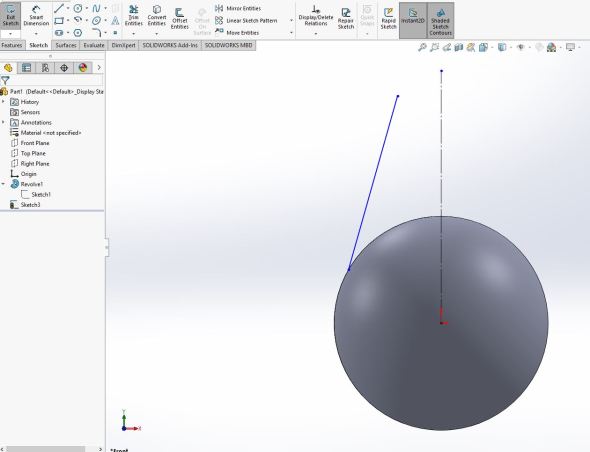
We’ve got a line with no real measurements associated with it, we’re doing this freehand today so it’s whatever looks good. If I divided my sphere into thirds, this would be the top third of the sphere roughly, you can raise or lower yours as you see fit, but be careful because that could come back to bite you in the next step if you put the line too far down the sphere.
Now click the line and you should see some handles to adjust the angles of the line. If you’re confused you can see the handles in grey shown below. Now we just adjust the line until we’re happy with the curve, again think light bulb-ish but feel free to make yours unique, we won’t bulb shame you here. Since these controls are a bit difficult to learn, I’ve labeled one of the ends of the line, note it’s the same thing for the other end or if I drew multiple segments, it would be the same for those as well. If you’re new I would use the left and right and the range of influence adjustments. What I’ve affectionately labeled the do you feel lucky dot, gives you access to all the adjustments at the same time and if you’re not careful can create some bad results and possible crash Solidworks, trust me I’ve done it one too many times to count, but I still use it from time to time. Only when I feel lucky though.
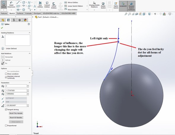
The controls for the spline that you just drew (see text above for a full explanation)
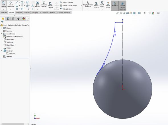
So now we have our curve! Let’s close this bad boy up. To do that we need to put a base to our bulb, I’m just going to be boring and draw a straight line, using the line tool, from the end of our spline to the axis of rotation (the line we set as for construction). You can see the end result below. I may go touch it up after, but for now if you squint really hard it looks light bulb-esque and that’s all I really want for now.
Okay, it looks pretty good! Now I’m going to revolve it using the center line as our axis of rotation and I should end up with something very light bulb shaped. Don’t worry sketchup people we’re about to do yours next! Since you should remember how to do the revolve (see our nose cone from this post) I won’t go into it with the pictures, but I’ll talk you through it. First, go to the features tab at the top of the screen (next to the sketch tab), don’t exit the sketch, we don’t need to and you’re just making more work for yourself if you do that. Click on the revolved boss/base tool, it should be the second from the far left tool and you will probably get this warning to close the sketch, I know it’s tempting to click yes, but we don’t want that so we will click no.
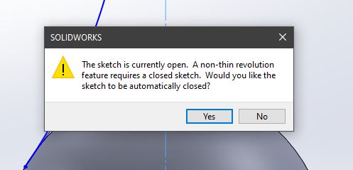
Don’t do it! Click no. We want a thin-revolve for this step.
Now you should see something like the first image below when you click it. If it doesn’t automatically select the axis of revolution, make sure you select that for construction line we created. Set the thin feature thickness to 0.2 in or 5mm, make sure merge result is checked (in the direction 1 section of the options) and click the green check mark, you should end up with something similar to the second image shown below.


Now, I’m not sure I like how thin the base of my bulb looks, so I’m going to edit the sketch and make it a little wider, again no bulb shaming here, but feel free to play around with it and find what works best for you! We won’t cover that here since all you do is drop down the carrot for the revolve thin operation you just did, then right click the sketch and say edit, feel free to do the same if you don’t like the way yours came out.
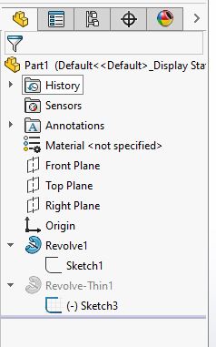
Use the triangle shape (what I call the carrot) to show the sketches that make up the operation you just did, in this case sketch 3 in the revolve-thin 1 operation is what I just drew so I right click and say edit.
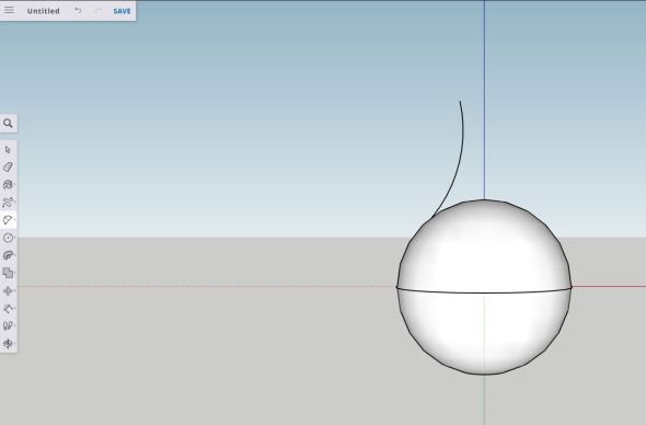
Okay time to get started for my sketchup people. Use the three point arc and we’re going to do basically the same thing we did in Solidworks. Go to the front view, then select the top third of the sphere, it will snap to the edge and say endpoint select the top part where you want the line to end, that will be your second click, the third click will dictate how curved the line is, so adjust that to your liking and you should end up with something like what I have below! Make sure your third click aligns with the axis, in this case you’ll see my x-axis is the red axis so it will say “on red axis.”
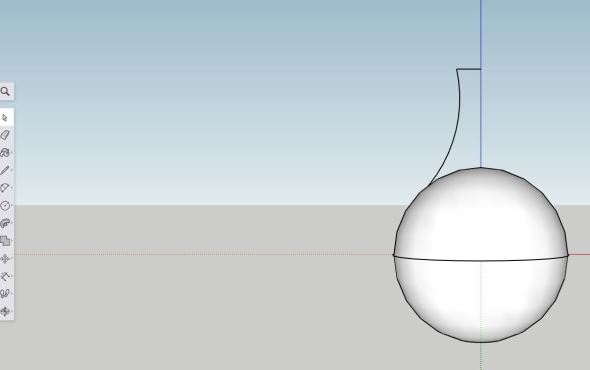
Next all we will do is draw a line using the line tool to connect the curve we just drew to the blue axis, again it should say on red axis since that is the x-axis color. It will snap to align with the blue axis and the red axis and you should have what we see below.
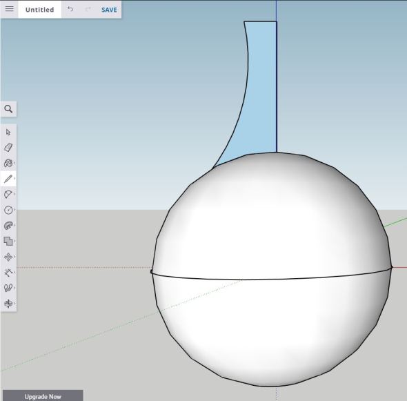
Now we need to do something tricky if we want to revolve this like we did in solidworks. We need to add a line following the blue axis into the sphere to close the shape. To do this you can rotate around the sphere, but I just used our handy line tool and clicked the end of the line we just drew and followed the axis down until it said “on blue axis” when my cursor was over the sphere, it was tricky so play around with it a little and rotate your view if you need to (the quick command for those of you using a mouse is to click the center button and drag your view around. In the end you should have something like this, a blue filled shape that we just created.
Protip: if you try to revolve this and it says you can’t do that with a curved surface, you can undo everything to the revolved sphere and just draw your sketch there, then revolve both the sphere and this added part that makes the bulb at the same time. You’ll end up with something like this when you do that.
Use the “follow me” tool and the guide circle we drew to revolve both the sphere and the base of our bulb (assuming you had to go back a few steps) if not, we’re just revolving the base of our bulb.
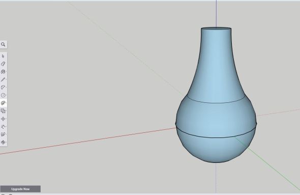
So now in both programs we have an ice cream cone looking object, let’s add the base of the bulb (the bit that screws in) and we can call it a day. Next week we’ll do something fun with the bulb, but it turns out writing solid modeling tutorials for two different but similar software is not easy.
Okay so in sketchup this time, we can just extrude the top face of our base, switch to a three point view and you should see something like this (again I circled in red the three point view I’m using).
The three point view I’m using is circled in red (right of the screenshot). We’re simply going to extrude the circle we have here a little bit to create the screw in portion of the bulb.
In the push/pull menu, we’re going to use the push/pull tool and extrude this base by let’s say 1 inch (25mm) , that looks about right to me so we’ll call it 1 inch (25mm) for this project. Doing that you should end up with something like this, note it says I extruded -1 inch because sketchup is weird like that and I’m working on the outside faces of my part (you can tell by the blue color my part is now).
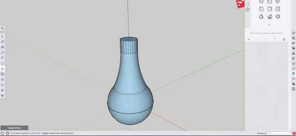
Extrude using the push/pull tool the top face (circle) by 1 inch (25mm) and you should see something like this.
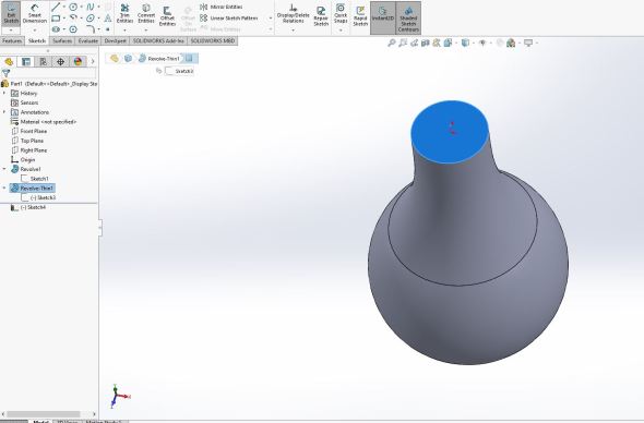
In solidworks this operation is just as easy, we’re going to click on the top face that we want to extrude (see below) and create a sketch on that face. Protip: since the face is flat we can create a sketch, solidworks will let you create a sketch on any flat face, not just in the planes you define.
Next click convert entities. This will create the circle for our extrude. Convert entities tool projects whatever you selected into the plane you are working so for example if I drew a circle in the front plane and created a sketch in the left plane and used the convert entities tool, it would be a straight line the length of which would be equal to the diameter of the circle since that’s all you see of the circle in the left/right planes. In this case since we are drawing on a plane parallel to the surface, our sketch is just the same circle that our base created.
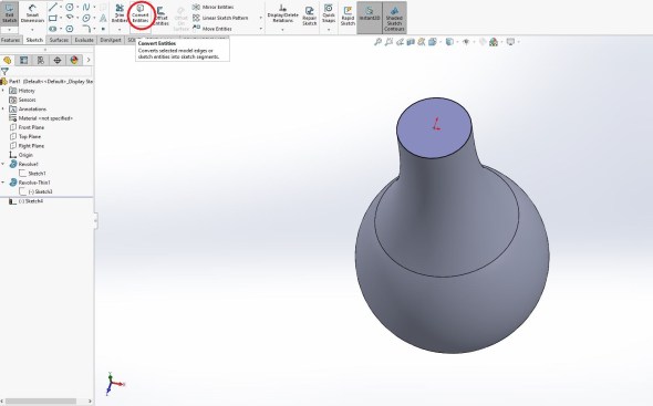
Use the convert entities tool (circled in red) to create the circle that we will extrude for our base.
Next, go to the features tab and use the extruded boss/base tool to extrude the shape to 1 inch (25mm). You should see something like the image in the left before you click the green check mark and the image on the right shows the completed operation.


Okay normally I would work to completion, but next we’re going to add in the screw shape at the base and that’s going to be quite a bit of work. Below you can see what the finished product will look like all rendered and pretty after I add materials (like glass, copper, and tungsten) to the part, I’ll walk you through how we get to that part next week. I added a few bits that we can’t do in Sketchup (free anyway), but we can do in Solidworks. I may cover how to do that some other time in a just solidworks capacity, but I’m not sure and right now we have between 4-6 weeks left for this little project of mine so we have plenty of time to figure it out.
Ironically when I don’t have to type all this out as I work, I can do this type of project in less than an hour, probably quicker. Blogging means it takes me hours to do where we got now, so I need to break it up so I can get other things done (this post for example, over four hours worth of work and I thought my know your spinal cord series took forever!). Next week we’ll finish it off and I already have other projects lined up, so this should be good!
The final product, basically what we’re aiming for, not too bad right? Rendering the final results make them look so much better than when you model them in the software, but it’s the same thing, just a little prettier. It does give you a good idea of what you’ll be able to accomplish if you decide to move away from the free software eventually.
Homework:
Create a thin walled cylinder with a hole on one of the circular faces (think cup) that has a radius of 3 inches (150mm) or a diameter if you prefer to work like that of 6 inches (300mm), a height of 6 inches (300mm) and a wall thickness of 0.2 inches (5mm). Oh, we didn’t cover how to that explicitly did we? That’s why it’s homework! If you can’t figure it out, don’t worry we’ll go over how to do it next week, but explore, have fun and don’t stop learning!


But enough about us, what about you?