Day 335: Solid Modeling – Week 6

Finishing our bulb today!! Wooo!!!
Welcome to week six! As always, this is a free class using FREE SOFTWARE. If you want to learn how to solid model, but couldn’t afford fancy or expensive software, then this course is for you. We’ll be taking things step by step so you (hopefully) will be able to follow along easily. If this is your first visit to my lovely series, then I would suggest you start at week one, which you can find in our incredibly helpful category Solid Modeling for Beginners. Today we’re going to finish our project from last week and make a super neat light bulb!
I should also point out again that if you’re just coming into this and for some reason want to start here we are using two solid modeling programs here. The first is solidworks, since these notes are primarily for my ongoing summer class. It’s not free, so for everyone else we are going to be using the free version of sketchup. There is a 30-day trial of the full version of sketchup, but we haven’t really used that yet and we may not. I don’t plan out that far in advance, I only plan a week ahead.
Now we are on week 6 of (probably) 10, maybe 12, but more than likely I’m only going to do 10 weeks since classes will be starting soon and I won’t have the half a day I need to devote to each post. As has been the theme of these posts, let’s do a quick recap (which keeps getting shorter as the weeks progress) and get started.
- Week one: I showed you that the most complex objects can be thought of as simpler shapes that make up that object. I did this by taking a seemingly complex shape (a cat toy) and modeling it using this principle.
- Week two: This week we revisited the cat toy, this time instead of making it in several steps, I did it in a single step, the whole thing in just one sketch. Then I explained why this is a horrible idea and that you shouldn’t do this.
- Week three: We finally did it. We got into the gritty world of solid modeling using the free software sketchup. I spent a considerable amount of time introducing some basic tools and more importantly I showed you how to navigate. I ended the post by showing you how to make a cube and you made a cylinder on your own.
- Week four: We made a thing! A rocket to be exact and you had more homework to make a mystery sphere, which I realized was harder to do in sketchup than I first envisioned.
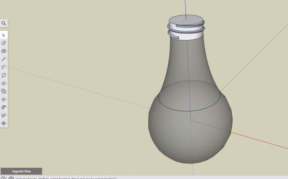
- Week five: We started making a light bulb! I gave the finished shot of what we were going for, but really we had to stop close to the end because I ran out of time. We made the basic shape and it was pretty much a light bulb already, but today we’re going to add the bit that lets you screw it in.
Disclaimer time: I do my best to explain things that I feel would be hard to follow. I try to do everything step by step and lay out the procedure to make it easy for you to follow along. I jump back and forth between solidworks and sketchup so you can see they are basically the same program. I’ve been solid modeling for a long time now, so while something may seem simple to me, it may not be to you. That’s okay, just ask in the comment section and I’ll be happy to clarify or if it is something that needs a long and thought out response, I’ll create a whole post for the question. My goal here is literally just to help YOU learn to use the software, so if you need help, just ask. If you want to remain anonymous I have the handy email form up at the top that you can use to ask privately.
Okay now time to get on with the show! If you’re following along you should have something right now that looks like this. The left is for those of you using sketchup, the right is for those of you using solidworks.


Today we’re going to add the threads that let us screw our light bulb in. This is basically the last thing we have to do, but as a bonus I’ll go over (somewhat) how to add in the wire inside the bulb. Unfortunately I don’t think the free version of sketchup gives us a glass option for the textures, so I’m going to look into it as I’m writing to see if we can figure out a work around so you too can have a cool looking light bulb with the wire inside.
That all said, let’s get into it. Now I tend to like to exaggerate the threads to make them show up a little better. If that isn’t to your style, you can do it differently, but I’ll walk you through how I do it, the only difference would be you would change the shape you’re extruding, you’ll see what I mean shortly, just keep that in mind as we work through this. So in sketchup first what we’re going to do is lay out the path that we want the threads to take.
Okay, well this may not mean much to you, but I’m back. I looked at the materials options we have for sketchup and while I found glass, I’m not completely convinced it fits the bill we wanted. So keep that in mind as we move forward that I have the materials set that I think will look the best for now. I’ll show you how I did it at the end of these notes.
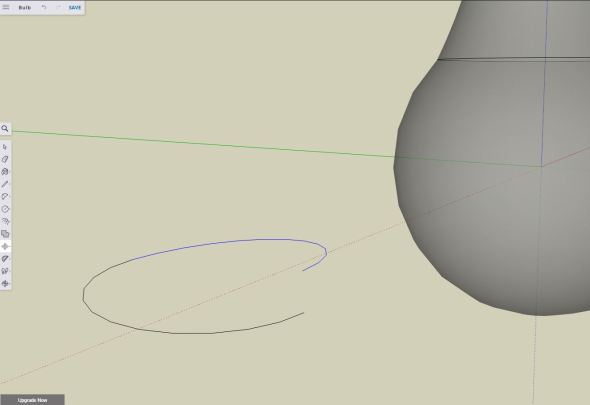
Back to our regularly scheduled program. First we want to create the helix that we will use to guide the shape, basically the tighter our helix the tighter the thread spacing will be and vice versa. I’m going to do what looks best to me, but you can play around with it and find what works best for you. First I’m going to use the 2-point arc (covered here) and draw a flat semi circle next to our bulb, if you’re using the same dimensions I am, the width is 1 3/8 inch (35mm almost exactly) and the “bulge” is 11/16 inch or 17.5 mm. Keep in mind you can verify this by drawing a semicircle on the top face of bulb (the base where we are going to put the helix) and you can find the exact dimensions of your base. So now you should see something like this.
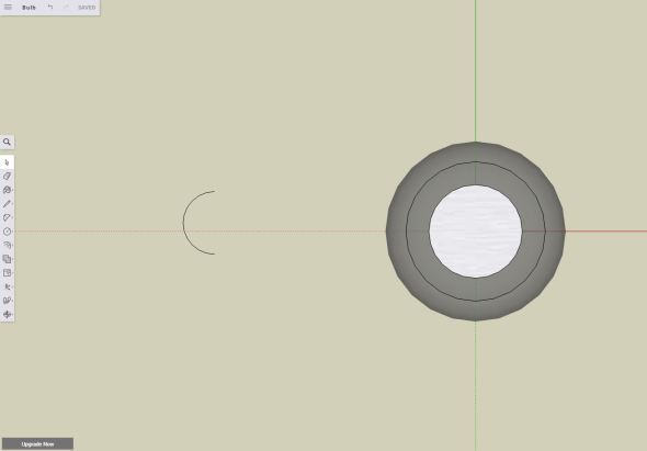
Notice my pretty semicircle sitting by itself to the left of my bulb here.
Okay it’s flat now and that’s a problem since a helix is a 3 dimensional arc. To solve this problem we are going to (very carefully) rotate it to the angle we want. The larger the angle, the more spacing we will have between threads and the lower our angle, the tighter the thread spacing. Let’s go into detail about how to do this.
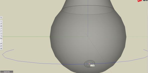
First I switch from the top view (what you see above) to a side view then I rotated slightly so I could see more than just a line. I then selected the rotate tool, you can find the rotate tool in the move menu as seen below
So you select the rotate tool and the icon looks like 2 protractors taped together. It works in two dimensions so if it looks flat, you’re working in a different dimension than you would be if it was standing up and down. Below you see what I mean, the icon is clearly up and down and first you click on the center point of the arc you drew. It should snap to this point (among other points it will try to snap to).
Since I am working outside a normal plane (IE a 3-point view) the icon doesn’t look flat, but I’m sure I’m in the plane created by the blue axis and the green axis (since they don’t label them x,y,z).
So I click that centerpoint and then I click directly above, you should see a dotted line being drawn from the centerpoint of the arc and the cursor. It will look something like what you see below. Once you’re up a little you can click again and this is the “handle” for your rotation. The first click (on the centerpoint of the arc) is the center of rotation), the second is the arm of your rotation, a shorter distance away from the first click will make it harder for you to rotate since it will happen much faster. You can type in the amount you want it to rotate and you’ll see the degrees rotated at the bottom right (where the measurements are normally at). Again, see below for that, I ended up setting mine at 5 degrees, feel free to play with it if you want.
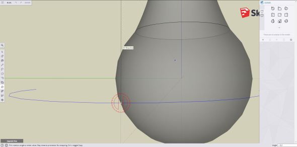
Rotate the arc from the center point (first click) and follow the blue axis and create your second point. The bottom right will display the degrees rotated (negative is the opposite direction) enter what you think looks best, I went with 5 degrees
Now one you complete that I went to the front view and you can see that we now have a semi circle that lives in three dimensions. From here we can copy and paste basically to create our helix. This part there are no screenshots, but should be easy, select the move tool and hold the control key (sorry mac users, I’m not sure what key this corresponds to for you). Click the arc and drag it, it will make a copy, just put it off to the side somewhere since we need to rotate it first. Now we select the rotate tool and rotate it by 180 degrees so it’s facing the first arc. That is shown below since it may be confusing.
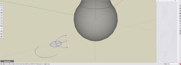
Click the centerpoint of the arc and then click some distance away (I clicked the center of the circle that the arc would form). Rotate it by 180 degrees and you’re almost done!
Once your arc is rotated the correct way, this part is comparatively simple. Select the move tool (see above move menu image if you don’t know where that is located) and you’ll want to select the lower of the two points, it should snap to this point. Click it and click the higher of the two points on the original arc that we drew. It should look something like this when you’re done.
Once you move the lower of the two points of the second arc to the higher of the two points of the first arc we drew you should see that it forms a full rotation and is now the helix shape that we want.
From here it’s copy, paste repeat until you end up with the number of rotations you need for your bulb. If you need a half rotation, you can undo what you just made so the two arcs are seperate, copy it and set it off to the side until you get full number of arcs you need then place the semicircle last. When it’s all said and done you should have at least 1.5 rotations to your helix, I went with two since it looked better to me, but as usual have fun with it and make it your own.
Hint: if you’re having trouble moving your part, you can turn it into a group by selecting the two lines you just put together and right clicking (they should still be blue, if they are not, try again) and click on the make group option.
I ended up using the make group option so I copied, moved it, and snapped it to the other helix (no need to rotate it this time!). Now I have two full rotations (seen below). I clicked on the top rotation so you could see that I made it a group. This is what it looks like when you make a group from seperate objects. It really makes it easier to move around.
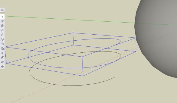
Once I made the bottom full revolution a group I copied it (hold the control key and use the move tool). I placed it off to the side, used the move tool to move the bottom point of the second arc to the top point of the first arc and now I have two full rotations.
Now I’m going to make this whole thing a group so we can move it to the proper location on our bulb. To do that, I repeat the same steps, select both, right click on one of the lines (everything you selected should still be blue, if not select them and keep trying), then click make group. Easy! Now we have our guide for the follow me tool.
We have a couple of options now, we COULD move it and use the follow me tool after you’ve placed it and created the shape, but I think it would be easier to do it here while I’m away from our light bulb to make it easier on myself. If you like to live dangerously go ahead and move it, the steps are the same.
Here’s the annoying part, sketchup won’t let you use the follow me tool if your objects are grouped like we just did to create this shape, so we need to “explode” them, right click your groups and select explode until they are individual lines again. Next we are going to draw our shape for the extrusion. Now to keep things simple I used a triangle. To do that, I selected the polygon tool (shown below, you’ll get a hexagon shaped icon, use control + to add faces, use control – to subtract faces. Since I want a triangle I subtracted 2 faces and was left with my triangle.
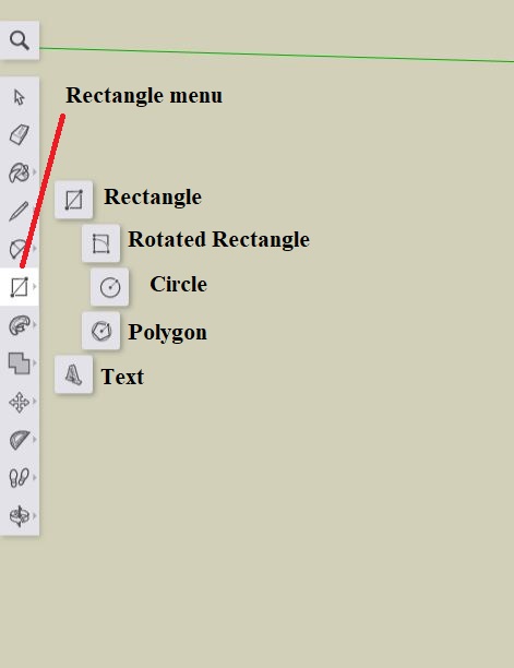
Selecting the polygon tool and using control + or control – will change the shape of the polygon you are drawing. I made a triangle, but hey go nuts, it’s your model.
Now all I’m going to do is switch my view until I am looking directly at the start of the helix (top or bottom, it doesn’t matter) then click on the end of the line to start the shape. It should say tangent to line or something similar. Draw the triangle shape to your liking, we can edit it and create a different shape if we want by using the line tool and the eraser tool, feel free to have fun, but I like my triangle shape for this so that’s what I’m using.
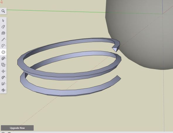
Once the shape is drawn, we just use the “follow me” tool and drag the shape around the helix. When you’re finished you should see something like what I have below. If you moved your helix to the bulb and did this step, you’re done!
Now the easy part! We are just going to group this and move it into place!
Once you’ve grouped it the easiest way to move this in place is to align the top inner point of the triangle to the top of face of your bulb. To do this, just select the move tool, which we should be familiar with by now! Then select the inner end point of the triangle on the top of your helix. Then what I did was switch to a top view, and centered it to the circle. It should snap into place and you’ll be able to see it as you move so just make sure it looks correct as you move it into place. It honestly shouldn’t be too bad so if you find you’re having trouble just rotate your view slightly and keep trying. In the end you should have something like this, it looks a little stubby, but I think it’s fine for now, maybe I’ll go change it later!
Now that I have it in place, it looks a lot more like a light bulb!
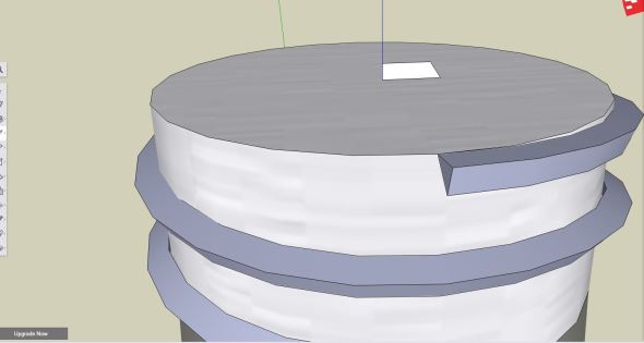
Now all we need to do is add the ground electrode at the top of the bulb and we have a perfectly good light bulb model! We can do this two ways, we could draw a small cylinder and resize the top face to give us the proper shape, OR we could use the revolve tool and revolve the correct cone like shape. I’m going with the latter option, but hey feel free to do it how you want! So I’m going to use my line tool and draw half the ground electrode on the top face (see below). It should snap to the center point so everything should work smoothly from here forward.
It’s the little things that make a solid model look real, adding the ground electrode is an important detail that makes the bulb look more bulb-like.
Once you have your shape, we need to draw the circle for the follow me tool to use, I’m switching to the top view to do this and I’m making my circle from the center of the top face out to the end of the shape I just drew (see below).
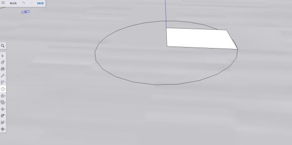
The circle I’m going to use with the follow me tool. I did it at a 3 point view so it wouldn’t end up on top of my other shape. I felt this would look “cleaner” but you can do it however you want and we can delete it afterwards anyway so it doesn’t matter
Next, I just use the follow me tool to complete the shape, revolve the part all the way around until it is a fully enclosed shape and you should have something like what you see below!
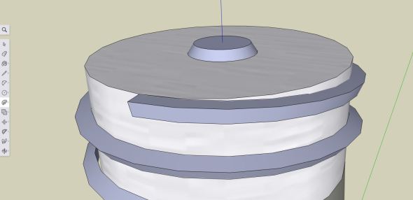
My ground electrode is all done now and it definitely makes my bulb look more recognizable.
And we are done! But wait, why didn’t we do this in solidworks yet? Well we can do that now, but solidworks makes this process super easy by using the helix tool so it’s much less involved. Let’s go through it really quickly. First let’s do the ground electrode since that’s the order I did it in originally with this drawing.
All I do is create a circle (left image) on the top face and extrude it up. Then I turn on draft, this gives me a smaller (or larger) angle at the top of the extrude than at the bottom (right image). I set mine to 33 degrees since that looked good to me and 0.2 inches or 5 mm.


Next to create our helix shape, we literally will use the helix tool! If we go to the features menu, we can click the curves menu carrot to give us the hidden options in that menu (see below) one of them is helix and spiral.
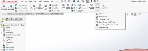
It’s the last option in the curves menu seen highlighted above.
When we click it, it will ask us to select a face/plane so we’ll use the top face that we drew the circle for the ground electrode above. Next all we do is draw a circle the size of the helix we want, in this case the circle will be the exact radius of the top face. Once we do that we can exit the sketch and then we will get several options to customize our helix, we can add or remove revolutions, increase or decrease the pitch, set it clockwise or counterclockwise, we can even have a variable pitch or taper the helix at the end. There’s so many choices it’s hard to list them all, but in the end we get something like this (while we’re in the menu).
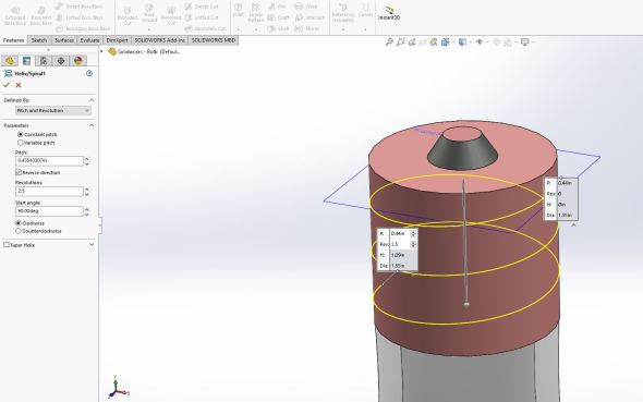
The helix tool makes this so much easier, you can see the options in the menu to the left and I adjusted them to what I thought looked good.
Once you have your helix path the way you want it, we can draw the shape we want to sweep across the helix. Since my helix started in the front plane I can go there and draw the shape I want, this time instead of using a triangle I think I’ll make something a little fancier.
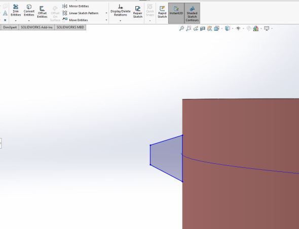
Here’s the shape I picked, it just felt right to me, you can do something different of course!
Then all we need to do is use the sweep tool found in the features menu to sweep the shape around the helix. Select the sweep tool from the features menu while you’re still in the sketch, it’s full name is swept boss/base. You should see a menu like below, just select the shape and the helix and the tool will do the rest (hopefully!).
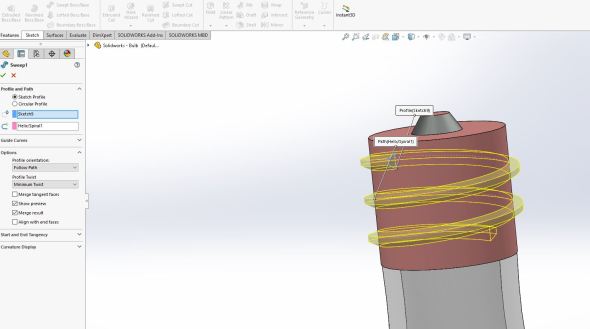
Here’s what you should see if you’ve selected the right sketches for this, technically the first sketch should be preselected since you were still in the sketch when you clicked the tool, all you should need to do is select the helix/spiral you created and the tool will do the rest.
Boom, done! Now let’s go over really quickly how to select the materials for your parts since I promised to do that at the beginning of the post. Since we’re in solidworks already let’s start there, on the right side of the screen you’ll see a globe with a bunch of colors on it, that has all your textures/patterns/colors you can use (hint: you can download others).

Hidden here is a vast selection of materials/textures and whatnots that you can choose from.
Here’s just the top view of the list, each of these folders have other folders inside with several options (left), one example is the plastic menu which has all sorts of different folders inside (right).


It’s really easy to use too, you can drag and drop and select different options for coloring, body, face, feature, etc. So play around with it and see what you like! For sketchup it’s a similar story without all the options unfortunately. We can’t complaint too much, it’s free software afterall and the paid version has quite a bit more texture variety. So let’s go through where that is located.
Similarly to solidworks, the textures/colors/whatever menu is on the right side, it’s official name is materials and it looks like a cube with an x through one of the faces (shown below). Like solidworks, if you click on any of these, you get several sub-options to choose from. Once you click on something you like you get a paint bucket icon and all you need to do is click the faces you want to color and the software will do the rest! Play around with it and see what you like.
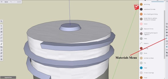
Here’s the materials menu with the major options listed, once you click any of them you’ll get a second menu with the list of choices. It’s isn’t a wide range, but I now have a glass bulb and a metal base.
Okay now we are done… oh wait we still need to talk about the wire inside the bulb. We’ll technically that’s your homework for the week! We already did all the steps you need to do to create it so you should be able to do this on your own!
Homework for this week: This step is just like the helix we created for our threads. Instead of doing a triangle or some polygon shape, we’ll just use a circle to create the filament! Just do the same steps (I would make the angle more narrow, but that’s just my preference!) and add a straight line to connect it to the base. If you need an example, the header image is done exactly how I would recommend yours look, but again you can make it as crazy or different as you want, it’s your solid model it doesn’t have to look exactly like mine! Have fun with it and we may go over how to do it explicitly next week.
Fear not! Last week’s homework will still be used next week. We’re nearing the end, but we still have a lot to learn so play around with everything we’ve covered today, do the homework and at the end of next week (or the week after) you’re going to have one very cool looking solid model and by the end of the course you’ll be able to model basically anything you can think of!
Until next time, don’t stop learning!


But enough about us, what about you?