Day 341: Solid Modeling – Week 7
If you’re following along you’ve made it to week seven! This course is taught using FREE SOFTWARE so if you ever wanted to learn how to solid model, this course is the one for you. If you’re just joining then you can find all of our classes listed here in our Solid Modeling for Beginners category. They are in reverse order, so start at the bottom. Today we are setting aside our lightbulb for a moment to create something to put it in. I’ve given up keeping what we’re doing a secret (since I always put the final product in the header image anyway). So with that let’s get to it!
Every week I try to point out how our class is structured and give a little recap of what we’ve covered these past few weeks. We are using two different programs in this course. One is solidworks, I’m teaching a small group how to use solidworks so this is primarily for them, but I wanted to make the class accessible so we’re also using the free version of sketchup. Technically you can get a free 30-day trial of the full version if you want it, but I’ve decided recently that we’re going to (attempt to) teach the whole class using the free version to keep the confusion to a minimum.
This is week seven already! Wow, so we’re going to have ten weeks total and frankly I need to plan the remaining two classes. This week and next I have planned, but we’ll see what the last two weeks hold. I like doing multi-week projects though it gives us a chance to make something really cool, like our lightbulb. So we’ll probably have one final two week project before I set you all free to solid model the world! (Hint, we can approximate it as a sphere so it’s not hard)
Okay time to get serious, here’s the recap for the past 6 weeks:
- Week one: I showed you that the most complex objects can be thought of as simpler shapes that make up that object. I did this by taking a seemingly complex shape (a cat toy) and modeling it using this principle.
- Week two: This week we revisited the cat toy, this time instead of making it in several steps, I did it in a single step, the whole thing in just one sketch. Then I explained why this is a horrible idea and that you shouldn’t do this.
- Week three: We finally did it. We got into the gritty world of solid modeling using the free software sketchup. I spent a considerable amount of time introducing some basic tools and more importantly I showed you how to navigate. I ended the post by showing you how to make a cube and you made a cylinder on your own.
- Week four: We made a thing! A rocket to be exact and you had more homework to make a mystery sphere, which I realized was harder to do in sketchup than I first envisioned.
- Week five: We started making a light bulb! I gave the finished shot of what we were going for, but really we had to stop close to the end because I ran out of time. We made the basic shape and it was pretty much a light bulb already, but today we’re going to add the bit that lets you screw it in.
- Week six: We finished our lightbulb! I taught you all how to make the basic bulb shape and in this class we added the part that screws in and the ground. I also showed you how to add textures so you could color your bulb glass. The homework was basically a repeat of what we did! You were to create the filament for the bulb so in the end you should have something that looks like the header image for that week.
Now my usual disclaimer: I do my best to explain things that I feel would be hard to follow. I try to do everything step by step and lay out the procedure to make it easy for you to follow along. I jump back and forth between solidworks and sketchup so you can see they are basically the same program. I’ve been solid modeling for a long time now, so while something may seem simple to me, it may not be to you. That’s okay, just ask in the comment section and I’ll be happy to clarify or if it is something that needs a long and thought out response, I’ll create a whole post for the question. My goal here is literally just to help YOU learn to use the software, so if you need help, just ask. If you want to remain anonymous I have the handy email form up at the top that you can use to ask privately.
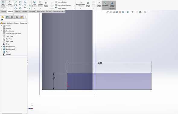
Okay now time to get on with the show! If you’re following along you should have something right now that looks like this. The left is for those of you using sketchup, the right is for those of you using solidworks.
Okay so today I said we were going to use week fives homework assignment. That assignment should’ve been super easy now that you’ve mastered all the other odds and ends of sketchup/solidworks! All you were supposed to do is create a thin walled cylinder (a cup shape) with a diameter of 3 inches (75 mm) I realized I screwed up the inches to mm conversion… oops! Hopefully you caught it and if not, you can always adjust or just go with it, the choice is yours! You also were told to give it a wall thickness of 0.2 inches or 5 mm and a height of 6 inches (150 mm), screwed up that conversion as well! Sorry!!! In the end you should have something like this!


Now we’re going to take divergent paths making this lamp, which is unfortunate since it’s always nice when the steps line up. However, there is a huge difference between Solidworks and Sketchup that we should discuss and it is why the lamp will take us some time since I’m covering it in both programs.
In sketchup we can draw anywhere in our little 3D world. I can easily move things I place and I’m pretty much free to do whatever. But… with great power comes great annoyances. Sketchup will let you draw wherever you want, but because it doesn’t constrain your drawing, you can end up placing it in the wrong planes! Think back to our headaches with the rocket for example or whenever we need to make a sphere.
Solidworks on the other hand limits you to drawing in a 2 dimensional plane. This constraint means that I always know where I’m working and keeps me from having to draw, redraw, re-redraw, until I get it in the right plane.
Both of these methods are used in industry. There are other solid modeling programs that use the same constraints (or lack thereof). So it’s a matter of preference. I prefer to use solidworks, but the fact that I’m free to draw and make in the world we’re in has its benefits and the first software I learned (autocad) took the same approach as sketchup. When it came time for me to learn how to use solidworks I was quickly annoyed by the limitation, but I’ve come to love it and prefer it as I’ve gotten further into my solid modeling.
Basically the bottom line is this, it’s all a preference and while I prefer the limitations used in solidworks, others hate it. So with that, we have two diverging paths to take to get our lamp done, making a huge headache for yours truly. Here’s how we’re going to solve this, we’re going to do it mostly the same way in both, but next week we’re going to diverge sharply as we will move things around all crazy like in sketchup (because we can!). You’ll see what I have planned, but for now know that next week if you like looking at how it’s done in both programs, things are going to get a little… weird.
Okay so we have our cup shape made (hopefully) with the right dimensions. I again apologize for that, it was a long day. So let’s get some of the frame going for our lamp and next week when we finish it we can add some final touches to it and make it look more, well lamp like. Plus we can customize it to your liking and I’ll walk you through all that next week.
First let’s add the hinge for the neck of the lamp. That cup we made, we’re using that for the lightbulb we made. We’ll get there, but for now let’s focus on adding the hinge. To do that in sketchup we can draw directly on the side face of our cup (the circular face).
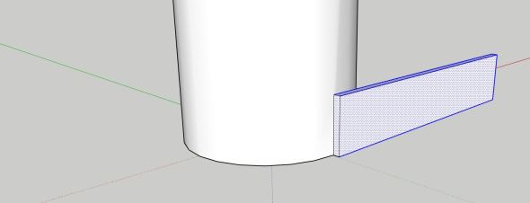
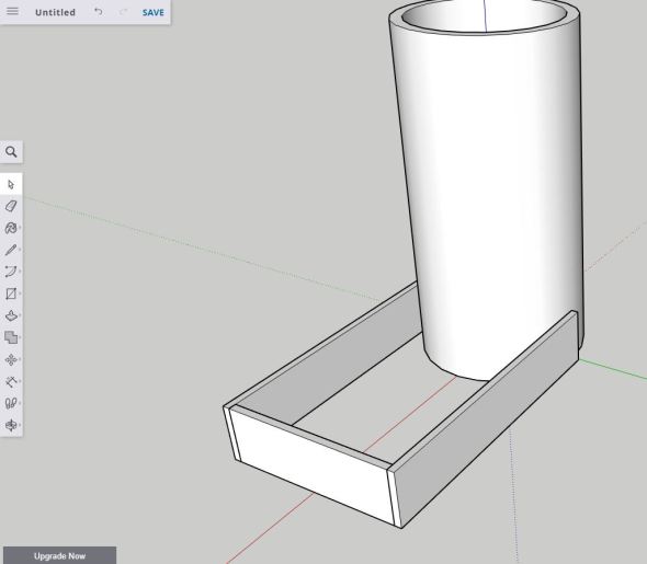
Here’s what you’ll end up with, don’t worry we’re going to take it step by step. I just want to show you the final result so you can keep it in mind.
To do this we’re going to use the rectangle tool and I drew mine to be 5 inches (125mm) by 1 inch (25mm) using the bottom of the cup shape and holding control. Holding control sets it to a corner rectangle, if you do not you’ll be asked to draw the rectangle using the center of the shape. We don’t want this. You can type in the dimensions like so: 5″, 1″ so 5 inches wide by 1 inch tall. If it comes out backwards, then just flip the dimensions you typed and it will work. Don’t forget the to add the comma or it will not like you. You should have something like this now.
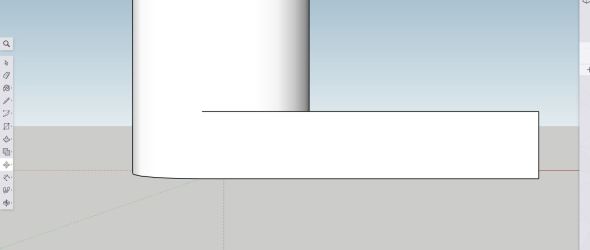
If we try to use the push/pull tool to extrude this, it will hate you. Notice our rectangle is open, well the shape joined with the circular face of the cup we drew. So we need to close the shape before we can extrude it. To do that, use the line tool (the pencil) and close the shape. It will snap to the ends, so this should be very easy to do. You should have something like what we see below.

Same as above, but I’ve just closed our rectangle.
Now we can extrude our shape using the push/pull tool. I did mine to 1/8″ or ~3mm you can do whatever you think looks best, it is after all your lamp! You should end up with what we see below or something close depending on how far you decided to extrude yours.
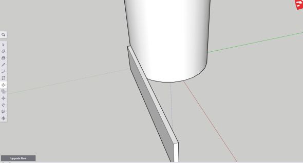
I extruded this 1/8″ or ~3mm do whatever you think looks best.
So now we have half of our hinge that we’re creating, to create the other half. First we need to group our part so we can easily move it or it will start stretching all weird (go ahead and try to use the move tool to see what I mean, just undo it before you continue). Select all the faces, the first few should be easy since they are on their own in space, the face that you don’t want to forget is the one near the cup shape (shown below).
Get all the faces!
Now you can group them, just right click anywhere on the part and select make group (shown below).
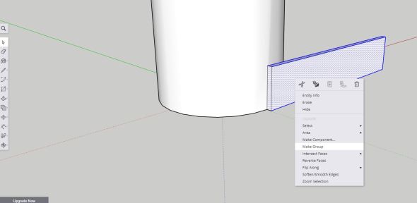
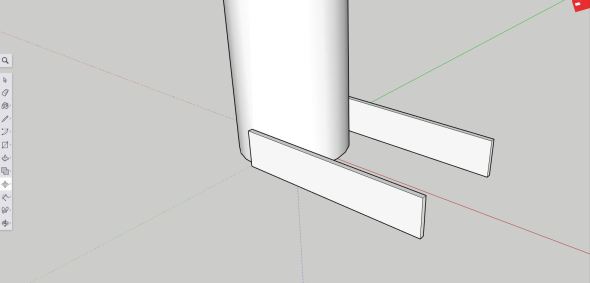
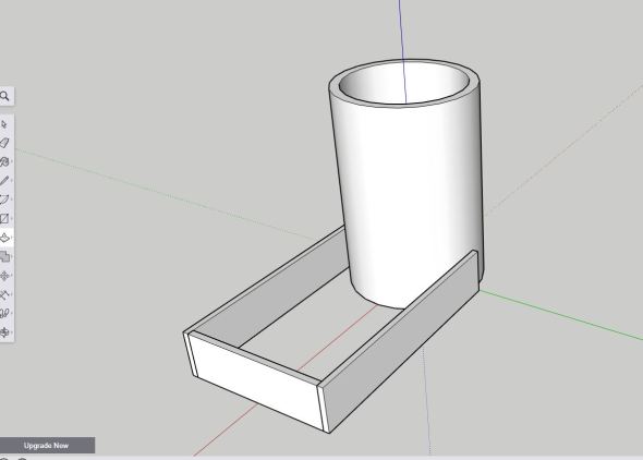
Now that you have your group, just use the move tool while holding control and drag it to the other side of the cup shape. Holding control will create a copy of it and once you move it into place you’ll have what we saw in the first image with the two bars.
Yay! Now let’s go ahead and do the same thing in Solidworks. Here’s where things get really different. We need to create a plane. To do that go to the features ribbon and select the reference geometry button, when you click it you’ll get a dropdown menu like the one shown below. Click plane (highlighted white below).
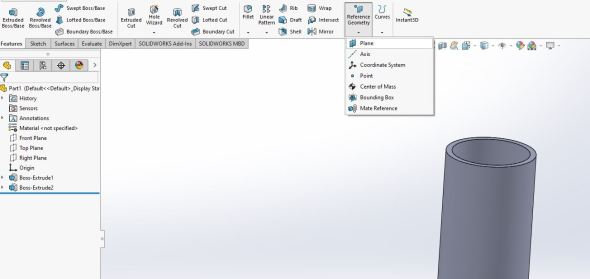
Here’s how we make planes
For the first reference we’re going to use the right plane and for the second we’re going to use the circular face of our cup shape. It will change the type of references so we need to fix this, you’ll want to select parallel to the right plane and tangent to the second reference (the face). You can see that below, notice parallel and tangent are depressed meaning that is how we are making the reference. You can see the plane I’m creating by the part. Below shows you how to set everything up in the plane menu to the left of the image.
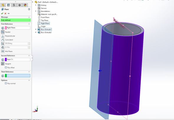
Our new plane is shown in blue on the face of the cup, just like we need to draw the hinge.
Once you click the green checkmark (near the top of the plane menu by the red x). You’ll have plane 1. Create a sketch on plane one and we’re going to do the same thing we just did in sketchup. Create a 5 inch (125mm) by 1 inch (25mm) rectangle at the center and bottom of the circular face as shown below.
Don’t exit the sketch, we can just extrude it from here.
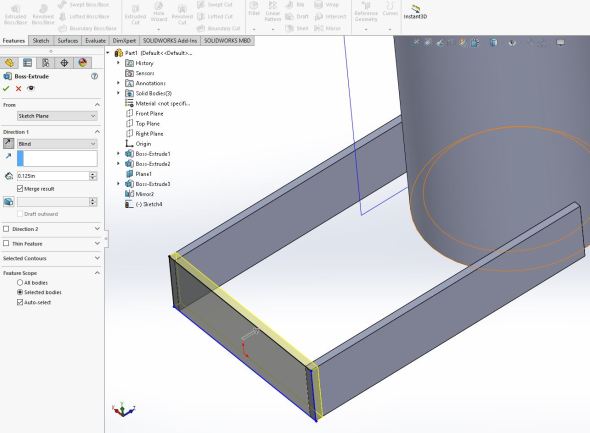
Now we can extrude the shape by using the extrude boss/base tool in the feature menu tab (top left of your screen). We’ll extrude it the 1/8 inch (0.125 inch) or ~3mm like we did in sketchup. You can see that operation below.
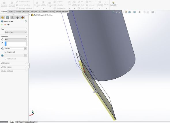
Prior to me hitting the green checkmark.
Now we just use the mirror tool to mirror it to the other side of the cup shape. The mirror tool is located in the features tab menu by the reference geometry button we just used. Once you select it, it will probably select the last operation we did, which is the boss-extrude, if not select it as a bodies to mirror (you’ll need to use the dropdown carrot to see it) and for the mirror face/plane you should select the right plane (assuming you were working from the origin and I hope you have been! It makes life much easier when you do, hint hint!!).
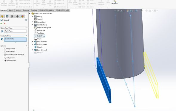
Here’s what you should be seeing, remember to use bodies to mirror or it won’t like you.
Click the green checkmark and like always and you should now have your two arms and we’re all caught up now in both software! Thankfully the next steps are basically the same. We’re going to join our two bars to make the remaining part of the hinge. To do this we can go a bunch of different ways. We could create a circle and extrude that to join the two, but I think I really like the bar look so I’m going to do that. That being said, you do whatever you think would look best. Since we’re here in solidworks let’s finish it and then we can jump over to Sketchup.
For this next bit, I just click the small face at the end of the bar (shown highlighted below) then we’re going to create a sketch.
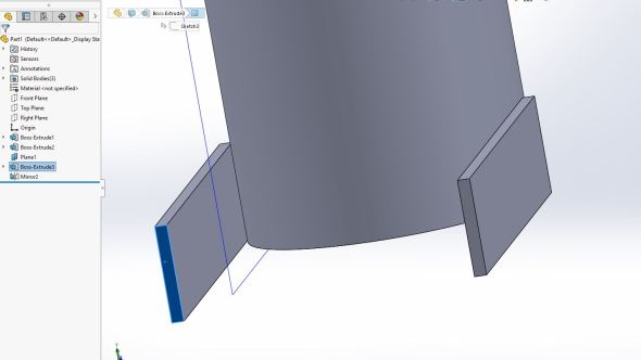
Create your sketch using this face (or the mirrored face, it’s all the same!)
Now all we’re going to do is create a rectangle from the outer top corner of one bar to the bottom outer corner of the other. You should have a box like what we see below.

We have our bottom to the hinge.
Now extrude that the same 1/8in or ~3mm as the rest of the bars (or whatever amount you extruded yours to, we can be different it’s okay). Now I liked that my bar was 5 inches, so I flipped the way I extruded my part, you can do it however you want, again it’s your lamp, but I figure this would look better to me. Just hit the green checkmark when you’ve got it the way you want.
Now we have our bar connecting the hinge.
Now we can do the same thing in sketchup. To do that you’ll use the rectangle tool and just go to the front plane and connect the two arms together. I did it using the inside faces since that seemed the cleanest way to do it, you can do whatever feels best to you. Then use the push/pull tool to extrude it the 1/8 inches or ~3 mm. Again, like before I thought extruding in toward the cup shape would look best, if you prefer the other way you’ll want to draw your rectangle using the outside points of the two arms. It will snap pretty easily so there shouldn’t be a whole lot of troubles. In the end you should have something like what we see below!
Now I’m thinking we extruded our cup shape a little too big, so I’m going to use the push/pull tool and remove 1.5 inches from the top of it. To do that I just click the push/pull tool and select the top face of the cup. Easy! Then for distance I enter -1.5 inches or ~40 mm. Again we’re freehanding all of this so it’s just a matter of what you like and what you think looks good!
After I took a little off the top so to speak. I think it looks a little better, but maybe you like the other way. As usual, the choice is yours!
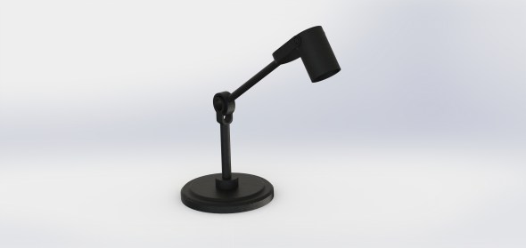
So I think that’s a good place to stop for the day. Next week we’ll finish this off and we’ll have a lamp! As usual I’ve skipped ahead and rendered the final product in Solidworks for everyone to see where we’re headed with this. I like solid modeling because we can create impossible objects, the elbow of this lamp is one of those things. It isn’t really possible to do, but I did it anyway because why the heck not.
Poor guy looks a little sad, hopefully you will all be making buddies for it!
Okay so homework for this week. This should be pretty easy, you’re going to create the first arm for the lamp the one I made longer). I went with 7 inches and a 0.5 inch thickness for the circle. If you’ve been following along it should be a snap. Then we can get into creating the impossible joint and the rest of the lamp next week. Ideally we will even be able to place our lightbulb in it and then have a full on lamp!
Good luck and don’t stop learning!


Great tutorial – thanks!
LikeLiked by 1 person
July 29, 2020 at 3:42 pm
Thank you!
LikeLike
July 29, 2020 at 5:16 pm