Day 348: Solid Modeling – Week 8
Left my lamp on in case you needed some light. While we didn’t finish the lamp today (boo) we got pretty far. We’ll finish it next week, but I don’t feel well so I needed to stop, sorry!
Welcome back or maybe welcome aboard! This is week eight of my online solid modeling course. As always we use FREE SOFTWARE for this class so no matter who you are, if you have internet access you can do this (seriously, it’s all cloud based so you don’t even need a fast computer!). If you’re just finding my little corner of the internet, never fear you can find all the courses in the super useful Solid Modeling for Beginners category. They get listed in reverse order, so work your way up from the bottom. Now that we’ve finished the intro let’s dive in!
As usual I want to start with the recap of all the previous weeks and sort of the justification for this class. We are using two different programs in this course. One is solidworks, I’m teaching a small group how to use solidworks so this is primarily for them, but I wanted to make the class accessible to everyone out there since solid modeling can be such a useful tool for just about anything you can think of! Because of that, we’re also using the free version of sketchup. Technically you can get a free 30-day trial of the full version if you want it, but I’ve decided recently that we’re going to (attempt to) teach the whole class using the free version to keep the confusion to a minimum.
The reason is the software UI looks slightly different, so we’re going to stick with the free online version to keep everyone on the same page. I already have to switch between solidworks and sketchup, so I would prefer to keep at that.
We’re nearing the end of the class and while I don’t think I’ve covered anything in particular with the depth I would like, I’ve covered almost everything I could with a good intro to how to use the tools. Today we’re going to finish our lamp and we can even put our lightbulb into it and have a completely finished product. I’ll leave the cord for the lamp up to your discretion but here’s a hint, you can use the follow me tool to create it!
Okay time to get down to business! Here’s our recap up to week 7 of 10!
- Week one: I showed you that the most complex objects can be thought of as simpler shapes that make up that object. I did this by taking a seemingly complex shape (a cat toy) and modeling it using this principle.
- Week two: This week we revisited the cat toy, this time instead of making it in several steps, I did it in a single step, the whole thing in just one sketch. Then I explained why this is a horrible idea and that you shouldn’t do this.
- Week three: We finally did it. We got into the gritty world of solid modeling using the free software sketchup. I spent a considerable amount of time introducing some basic tools and more importantly I showed you how to navigate. I ended the post by showing you how to make a cube and you made a cylinder on your own.
- Week four: We made a thing! A rocket to be exact and you had more homework to make a mystery sphere, which I realized was harder to do in sketchup than I first envisioned.
- Week five: We started making a light bulb! I gave the finished shot of what we were going for, but really we had to stop close to the end because I ran out of time. We made the basic shape and it was pretty much a light bulb already, but today we’re going to add the bit that lets you screw it in.
- Week six: We finished our lightbulb! I taught you all how to make the basic bulb shape and in this class we added the part that screws in and the ground. I also showed you how to add textures so you could color your bulb glass. The homework was basically a repeat of what we did! You were to create the filament for the bulb so in the end you should have something that looks like the header image for that week.
- Week seven: We used our homework from week five (told you we would!) to make the bulb holder thing of our lamp. Frankly I’m not sure what the actual name for that part of a lamp is, but we’re going with bulb holder thing damn it. We learned how to move things around in sketchup which we cannot easily do in solidworks and we covered why this is a good and bad thing.
Now my usual disclaimer: I do my best to explain things that I feel would be hard to follow. I try to do everything step by step and lay out the procedure to make it easy for you to follow along. I jump back and forth between solidworks and sketchup so you can see they are basically the same program. I’ve been solid modeling for a long time now, so while something may seem simple to me, it may not be to you. That’s okay, just ask in the comment section and I’ll be happy to clarify or if it is something that needs a long and thought out response, I’ll create a whole post for the question. My goal here is literally just to help YOU learn to use the software, so if you need help, just ask. If you want to remain anonymous I have the handy email form up at the top that you can use to ask privately.
First let me just say, we’ve made it to week eight and it’s been a pleasure teaching all of you. I’ve got some good feedback and I’ve had a lot of fun doing this. For those of you who don’t follow my blog regularly though, I’m going through some shit. I’ve had a flare-up of … something. I thought it was psoriasis, but it was recently pointed out that the symptoms are a lot like lupus, which my uncle had so that’s … fun. In any case I don’t particularly feel well and these posts take a LOT of energy for me.
Normally that’s fine, but lately I’ve had no energy and breathing seems like too much work for me. It’s not fun, but the show must go on and I really want to do this because I love teaching so much. That said if today’s post is short (remember I do the work as I’m writing this so you all can see I make mistakes too and how to correct them), I apologize, but I’m confident that we can at least put the finishing touches on our lamp so you too can have a finished product. Hopefully I can get over this soon and we can dive into our last project together which will run the two weeks left in our little series. I want to make the last two weeks something fun, so I need to come up with what we’ll make between now and then. It just depends on how I’m feeling too.
Okay enough talk let’s get this lamp done!
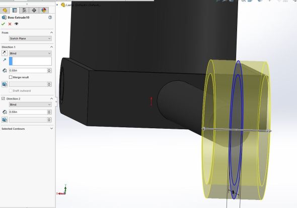
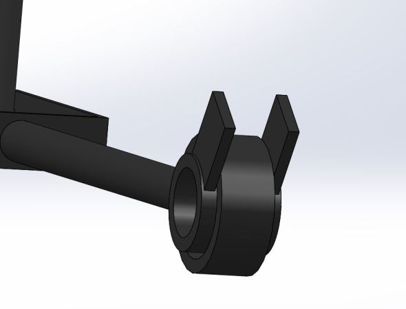
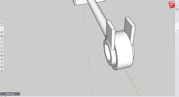
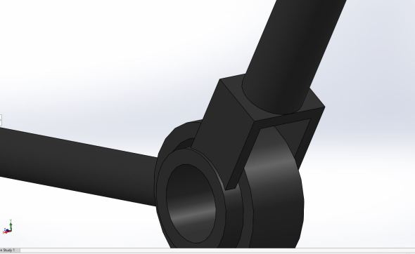
If you’ve finished the homework we should have the arm of our lamp all nicely attached and we can add what I deemed the “impossible” joint for the middle of the lamp. Now, I realized after the fact that I never included a good photo of the impossible joint, so let’s take a look at the fancy solidworks render of it since I love how solidworks renders things.

Basically it’s a ring inside of a floating ring, hence the impossible joint. Frankly, I just like how it looks, but if you want to do something different for your joint, the steps are the same and feel free to explore. If you like what I did and want to do the same, well let’s dive into how to do this.
The creation of the joint is pretty straight forward, what we’ll do is create at the base of our arm that I had you make for homework the larger of the two rings, then we can create the inner ring and work on the base of our lamp. Now if you notice my renders from last week and today, the base had some flourishes that made it look a little more interesting than a plain ol’ lamp base. You can do this too! I’ll walk you though a little of it.
Last week I said I made my arm with a diameter of 0.5″, well I didn’t like that so I modified it to 0.75″ or ~19mm. Then I extruded it using the push/pull tool (or extrude boss/base tool in solidworks) to 7 inches. That seemed like a good length to me, but you can make it however long or short you want, it is your lamp after all! So basically you should have something right now that looks like this in sketchup (left) and solidworks (right).


Okay first let’s do this in solidworks since it’s easier, then we can get it done in sketchup. It’s basically the same, not going to lie, but with sketchup we can place things at weird angles we need to be careful.
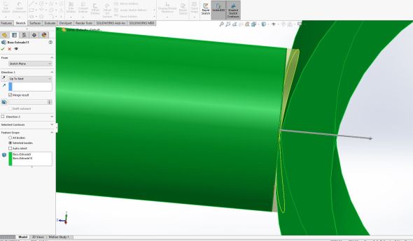
In solidworks I create a sketch in my right plane, then I sketch two rings near the end of the shaft, the first is the larger with a 2.5″ radius or ~65 mm, the inner ring is at the same center as the larger circle, it should snap to the center so keep that in mind. That will have a 2 inch radius or ~ 50mm.

Now the two circles you drew should be concentric, so if you move one the other should move with it, this is important for this next step, we’re going to make the larger ring tangent to the end of our lamp arm as shown below. Everything should line up as you see here, if not your inner ring was probably not set to be concentric to the larger ring, you can fix that by selecting the two rings and making them concentric.

Notice the green tangent icon showing up on the larger circle. This lets me know that I set it properly (plus it looks tangent to the end face of the lamp rod so I can be confident it’s correct.
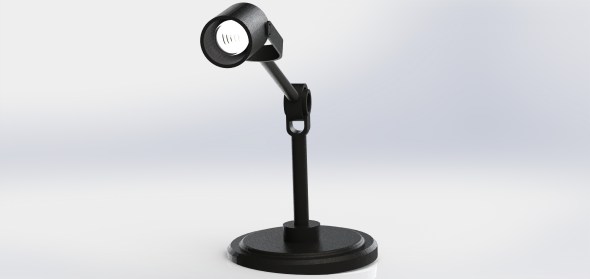
Now we have the first half of our joint! We just need to extrude this. HEED MY WARNING! Okay, maybe that was a little intense, but you are drawing in the center of the rod face, so we need to extrude this in TWO directions so we have everything the right widths (see the image below, you can see that the sketches we just made were in the middle of the arm not on the outer edge, this is okay and we want this, so don’t stress! We just need to extrude it two ways so it comes out correctly.

Our sketch lives in the middle of this rod, so when we extrude it, we need to go both directions to get it right or we’ll end up with an off center joint!
Doing this is super simple! Just go to the extrude boss/base tool in the features menu, you should be super familiar with that tool by now. Next we’ll extrude in one direction blind and by 0.5 inches or 12 mm. Before we accept it though, we click the unchecked box next to the heading Direction 2 and we’ll do the same, extrude blind for 0.5″ or 12mm. Below is how I have mine done, you should have something similar even if you’re making your own joint.
To the left you can see how I set mine up and to the right, we get a preview of how it extrudes, you should have something similar.
Just click the green checkmark and you’re done and we can move on to the second part of the joint! Just sit tight while we go over how to do this in sketchup (or just skip ahead, your choice).
In sketchup the steps will be very similar, it’s just the way we extrude this and the plane we draw it in that changes. So let’s walk through that really quickly.
First we want to switch to the side view or the view that looks similar to the solidworks view we just used, for me that’s actually the front view, but you may have drawn yours in a different set of axes, so it may be difficult since sketchup doesn’t name them. Now use the circle tool and rotate your view slightly so you can see the end face of the lamp arm you drew. You should be able to snap to the center point, if you carefully (CAREFULLY!) move your cursor to the right of it (or left depending on how you’re looking at the model) it should let you draw your circle where the center of the circle is offset from the center of the rod. This is important since we don’t want to have to try to line everything up afterward. See below for what you’re aiming to do.

Selecting the circle tool, I hovered over the center of the end face until it snapped to center. Then I can move my mouse away from the face along the red axis (notice the red dotted line) if I were to draw a line directly though the circle I plan on drawing, it would be perpendicular to the green axis, hence the circle tool shows the color green. Depending on your axes setup, you should see the same or something that fits the way you did your lamp.
Now I draw my circle! Remember sketchup does things by radius, so the inner circle has a radius of 1 inch or ~ 25mm and the outer larger circle has a radius of 1.25 inches or ~30 inches. They don’t need to be up against the end face of the rod yet, we can move them so just draw them however far away from the end face you want (it just seemed easier to me to do it this way). See below for how mine looks.

Just draw it anywhere as long as the center of the two circles lines up with the center of the end face of the rod, we should be easily able to move it into place.
Now it’s time to move it so it lines up with our end face. Just select the move tool and the space between the two circles and they will move as one. Since our center lines up with the center of our end face, all we need to do is translate it along the red axis. It will snap to the end face and you should have something that looks like this shown below. Note I was in the process of moving mine when I took this screenshot, the red dotted line tells me I’m moving parallel to the red axis. Friendly reminder that’s just how sketchup works and it’s useful information.

Your circles will snap into place just like mine did. Or at least they should, if they don’t you can always undo the move and try again!
Now we use the push pull tool to extrude the surface between the two circles (the one highlighted in blue dots above). Same as with solidworks, we will extrude in one direction 0.5 inches or ~12mm, then we will do the same in the other direction as shown below.


Now we are caught up, BUT we have that blue/white face on the center of our joint so it isn’t hollow, you can just click on it and hit delete and you’ll be left with just the joint
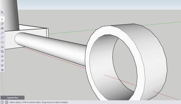
Just select the blue face and delete it. If you’re left with a black circle in the center (which you should) you can delete that too and you’ll end up with exactly what we have here.
Now for completeness, we need to fix the end face, we have a flat face up against a circular face, so there will be a gap! Let’s take a look at what I mean (below)

Eww, it looks so awful!
To fix it, use the push/pull tool and bury the face into the circle, just select the end face of the rod (this may be a little difficult so rotate your view so you can see it). Be careful not to extend too far or you’ll end up coming through to the other side, just do it enough that the faces are well connected. When you’re done you should have something that looks like what you see below.

Much nicer!
Okay now let’s do the same thing for our solidworks version since we have the same problem over there (see below).

Different software, same problem.
Luckily in solidworks we have a more… elegant way to solve this. Create a sketch on the end face (the one that faces the circle). Then convert entities, you should end up with a circle that is the outline of that face (shown below). It’s a hard shot since the joint is in the way, but you should be able to see what I did.
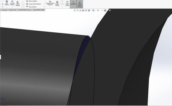
Notice the black circle and the dark blue face I selected to make my sketch and convert entities.
So now I have a circle the same diameter as the rod. We’re just going to use our favorite boss/base extrude tool to do this part. Instead of selecting blind though, we are going to select up to next. Up to next means it will extrude until it touches the next part. As long as the next part covers the entire face we are extruding, this will work. Since we designed the joint to be wider than our rod, there should be no problems. Below you’ll see how that looks. You’ll notice I merged the result and selected the bodies myself, you don’t need to do this, but I had something in particular in mind when I did this.
Notice it only extrudes up to the surface of the next part. This is incredibly useful if we have a thin walled part that we don’t want our extrusion to pass through.
Okay so in the interest of time and my sanity (okay, that was gone a long time ago, but work with me here), we’re going to skip the inner joint. Fear not, it’s the exact same process without all the extruding and burying faces, you’re just creating the inner ring. In solidworks you’ll do that in the right plane (assuming you were drawing yours like I did mine). In sketchup it’s even easier than the first ring we drew, you’ll just draw the circles on the outside face of our joint (We need to extrude in two directions since this will be a longer extrusion, but it will make it easier to draw if we just use the outer face to find the center, or you can try to find the center like we did when we drew the first set of circles, your choice!).
Okay so dimensions, if you want to do it exactly as I did, the larger circle is 1.75 inches or ~45 mm, the smaller circle is 1.25 inches or ~32 mm. In solidworks I drew my sketch the same way I’m suggesting in sketchup, by using the face of the outer ring we drew. You’ll use the extrude tool or push pull tool to extrude 0.25 inches or ~6mm out from the face and 1.25 inches or 32mm intward to the other side of the joint. You should have 0.25 inches or ~6mm of overhang on either side.
In the end you should have something that looks like what you see below. On the left is the sketchup version, notice my circle is in the same plane as the end of my larger ring. The same thing is shown on the right, this time I am showing the extrude so you can see that I did the same thing here, I drew the circles on the plane created by the outer face of the ring.


So same routine as before, in sketchup we have a blue/white (depending on which side you see it from) face that is extra, you can delete it and the black circle it leaves if you want to clean up the sketch some.
Well now that the hard part is over, it’s time to add the rest of our joint and finish this off! Now we’re making the boxy half of our joint (see the first part of it below).
Luckily for me I made these next steps super simple (Yay for me being smart!)
Since I’m in solidworks right now, let’s do it there first, All I did was create a sketch on the outer face of the larger ring in our joint (the one we used to create the inner ring). Notice how the two blocks above touch up against it? Yep, that’s because they are in the same plane. Create a sketch and all we’re doing is freehanding our box. The two bottom points touch the ring and are set to be coincident to the the ring, then we just draw the rest of the box. I literally did this freehand and went with what looks best, but I added dimensions just now to see what it came out as and it looks like I came pretty close to 1 inch (25mm) exactly for the width and 1.5 inches (38mm) for the height. It’s not exact, but that’s what I get for freehanding it. You don’t have to do it that way, but using the line tool instead of the rectangular tool meant I could draw it rotated without having the extra step of needing to rotate it into place. You can see what I did below, the box doesn’t pass through the inner face of the inner ring so I didn’t have to get fancy with it.
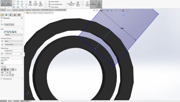
Notice my dimensions are not exact, it’s okay I freehanded this using the line tool, you can use the rectangular tool if you want, but this was easier to get it at the angle I needed.
Next, we extrude it 0.2 inches or ~5mm. I only merged the part I am extruding with the inner ring (going to feature scope and selected bodies to select the inner ring). You don’t have to do it that way, but when I wanted to render it I thought it would be useful to be able to move it around so I created an assembly. Unfortunately I won’t be covering that here, but just know it exists.
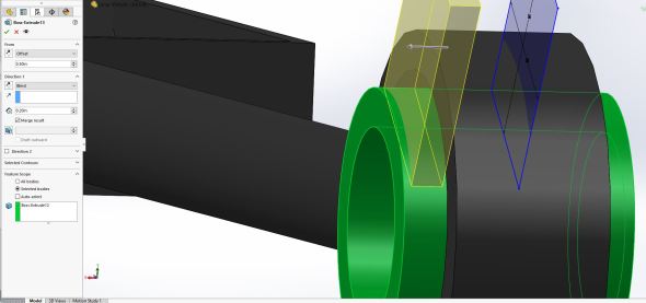
Okay so my secret is out, I drew it on the middle plane, but I offset it to the same face, so you can just draw it over there instead and save the headache.
The process is repeated in the other direction and you end up with the two square bits we saw above in the finished product.
Okay so now to do that in sketchup, it is exactly the same process! Well… sort of. Instead of drawing the rectangle directly on the face it’s easier to draw it on the same plane, but above the part and then to move it in place. Sketchup will freak out if you draw it right on the face like that, go give it a shot and see what I’m talking about. So same process as when we drew the circle to create the outer ring. We can select our rectangle tool then we line up with the face and carefully move off of it. We will get a dotted line the color of the axis we’re going to draw on and it will say “from point.” I find it easiest to start drawing the rectangle and typing in the dimensions like before. So width is 1″ (25mm) and height is 1.5 inches (38 mm) and you would enter it 1″,1.5″ and hit enter, then you should have what you see below (maybe a different amount away from the part, but that’s fine. I already used the push/pull tool to extrude this to 0.2 inches or ~5 mm.

We will just copy this and move it into place, but first we need to move it down so we only need to move it one axis at a time.
Okay so we have our component, so we can do what we did with the lightbulb and group the object to make it super easy to move. Carefully select all 6 faces of the part (you can do it in one selection, but be careful not to select anything else). Right click on one of the highlighted faces and select make group. Now we can use the move tool (just like we did with the light bulb) and move it into place. You should have something like what I have below.

Carefully move it in the single axis (you should have a single colored dotted line letting you know you’re moving in the single axis). Then just move it into place.
Once it’s in place, hold the control key (sorry mac users, not sure what your control key is!) and using the move tool, we can move a copy of the part over to the other side. You should now have what I’m showing below. You can type in how much you want to move it, so I moved it by the green axis and entered the width of the outer ring to offset it (1 inch or 25mm I believe).
Just copy the group by holding the control key while using the move tool, when you see the words “by green axis” just type in the amount you want to move it by and hit enter. It should place it right where I have mine!
Okay, I really wanted to finish this lamp, but I’ve got to call it a day. It’s been a bit of work! So next week we will finish finish the lamp, I’ll walk you through making the base and how to add some touches to it. Unfortunately I realized I cannot import other parts from sketchup free! OH NOES! Not to worry, we can export it and put it together different ways so too will be able to put your lightbulb in your lamp when we’re done.
Homework for this week:
Super simple, finish off this joint. To do that you’ll place a piece across the two rectangles we just made, then draw a circle in the center and use the push/pull tool to create the second arm of our lamp. When you’re done you should have something like what you see below.
As usual, you can make your dimensions whatever you want for the second arm. The piece that goes across the two rectangles we just made should be determined by the width and the spacing so you’re looking at a 1 inch (25mm) by 1 inch (25mm) rectangle that we extrude 0.2 inches or 5mm. For the arm I used a circle with a diameter of 1 inch (25mm) or 0.5 inch (13mm) radius since sketchup likes working using radius. I extruded this arm to 7 inches or ~175mm, but as always you can do whatever you like it’s your lamp!
Again, I apologize, I really wanted to finish this off today. I just really don’t feel well! That just means we’ll have more time next week to put in some details though that I would’ve had to gloss over here, so no big deal. I think I know what I want to do for our final week too, so that’s good news.
Until next time, don’t stop learning!


But enough about us, what about you?