Day 363: Solid Modeling – Week 10
This has nothing to do with today’s post, it’s just the most cursed thing I’ve created in SolidWorks.
All good things come to an end. It’s week ten and officially our last post in this quick run through. As always we use FREE SOFTWARE to do this, so if you’re just joining in you can find the full course in the Solid Modeling for Beginners category and you don’t need to spend money to learn. Since this is our last post I wanted to do something a little different today, let’s get started!
By now you know that I start all the posts with a little (long) blurb about why I’m doing this. These are technically my solidworks class notes. However, since I wanted to make this accessible to everyone, I figured I would put in the effort to also teach anyone who wants to learn solid modeling using the free software Sketchup. For my class, we’re using the extremely expensive professional software, solidworks.
This course was taught using the free version of sketchup exclusively. That made it easier because the paid version UI is somewhat different from the free version. Since I was already bouncing between two different programs, I didn’t think adding a third would benefit anyone. So as usual, let’s get started with our recap.
It’s the final recap!!!!
- Week one: I showed you that the most complex objects can be thought of as simpler shapes that make up that object. I did this by taking a seemingly complex shape (a cat toy) and modeling it using this principle.
- Week two: This week we revisited the cat toy, this time instead of making it in several steps, I did it in a single step, the whole thing in just one sketch. Then I explained why this is a horrible idea and that you shouldn’t do this.
- Week three: We finally did it. We got into the gritty world of solid modeling using the free software sketchup. I spent a considerable amount of time introducing some basic tools and more importantly I showed you how to navigate. I ended the post by showing you how to make a cube and you made a cylinder on your own.
- Week four: We made a thing! A rocket to be exact and you had more homework to make a mystery sphere, which I realized was harder to do in sketchup than I first envisioned.
- Week five: We started making a light bulb! I gave the finished shot of what we were going for, but really we had to stop close to the end because I ran out of time. We made the basic shape and it was pretty much a light bulb already, but today we’re going to add the bit that lets you screw it in.
- Week six: We finished our lightbulb! I taught you all how to make the basic bulb shape and in this class we added the part that screws in and the ground. I also showed you how to add textures so you could color your bulb glass. The homework was basically a repeat of what we did! You were to create the filament for the bulb so in the end you should have something that looks like the header image for that week.
- Week seven: We used our homework from week five (told you we would!) to make the bulb holder thing of our lamp. Frankly I’m not sure what the actual name for that part of a lamp is, but we’re going with bulb holder thing damn it. We learned how to move things around in sketchup which we cannot easily do in solidworks and we covered why this is a good and bad thing.
- Week eight: We made the “impossible” hinge! It’s the thing I think that gives this lamp a little character. The homework was pretty straight forward, all you needed to do was create the remaining arm for the lamp. There was a lot of moving things around and figuring out how to work in the sketchup space, so it was a good way to further introduce some of that.
- Week nine: We finished off our lamp. At this stage we know how to do all the basics and we did them well. We resized things, moved things, even freehanded the cord for the lamp. I took a little more of a hands off approach in this week because by now you were already familiar with the tools and I wanted you to get the chance to see what you could do instead of just copying what I was doing.
Now my usual disclaimer: I do my best to explain things that I feel would be hard to follow. I try to do everything step by step and lay out the procedure to make it easy for you to follow along. I jump back and forth between solidworks and sketchup so you can see they are basically the same program. I’ve been solid modeling for a long time now, so while something may seem simple to me, it may not be to you. That’s okay, just ask in the comment section and I’ll be happy to clarify. Or if it is something that needs a long and thought out response, I’ll create a whole post for the question. My goal here is literally just to help YOU learn to use the software, so if you need help, just ask. If you want to remain anonymous I have the handy email form up at the top that you can use to ask privately.
Today I’m going to switch gears somewhat. See, the first two weeks I taught you how to think about HOW to solid model. The next week I broke down the location of some of the tools, then for the remainder of our time we’ve been using those tools to create stuff. It’s been fun! However I want to take a step back this week and instead of making something, I want to review where everything is located and what it does.
Everything we’ve made I did with a purpose. In terms of sketchup, the rocket gave you a chance to learn how to use the push/pull tool and a small intro into the follow me tool. The lightbulb introduced the follow me tool and we also learned how to group and move things, it also gave us an intro into textures/colors. Then the lamp put it all together and we created something very substantial using all the tools and then moving the lamp around to place it where we wanted it.
Basically you’ve learned all the main tools and we’ve thoroughly used them. However, I haven’t covered some of the other tools available to you. There was a lot of reasons for this, time being the main issue, but also because they weren’t particularly useful for my curriculum so we skipped over them. Today I’m going to show you where all the tools are located (in both solidworks and sketchup) and give you a brief description of them. I think it will be a good way to wrap everything up so you can reference this post if you need to figure out where something is located. So let’s dive in.
Sketchup
First sketchup, some of these tools we’ve already introduced/covered, but we’re doing all of them so you have a complete reference post here for you to use. First up, let’s cover the left side (shown below).
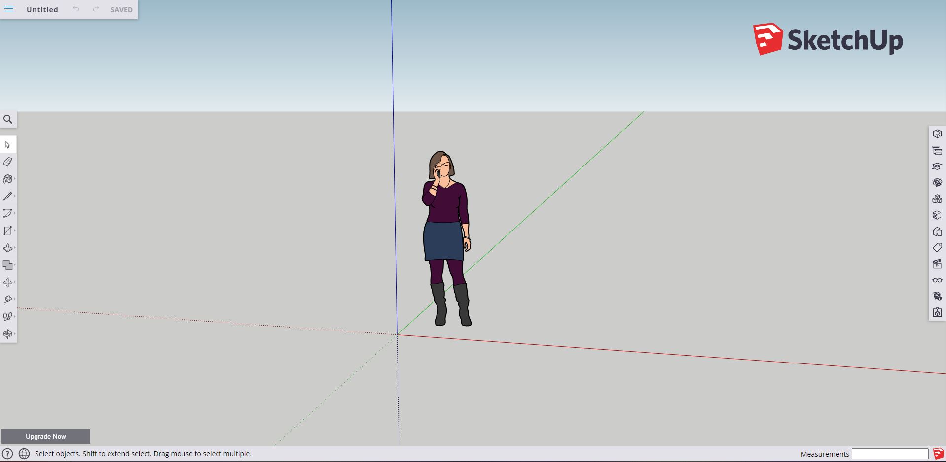
Our little sketchup world
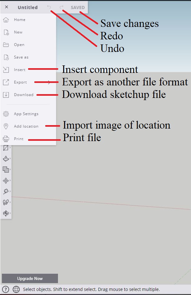
If you click the three lines at the top left of the screen you’ll get a little dropdown menu. (shown below). Home takes you to the main screen. New creates a new part. Open lets you open a part. Save as gives you the option of saving the file with a different name. Insert let’s you add other parts into the part you’re working on. Export gives you the option of exporting your file as (among other things) an .stl part so you can 3D print it, use it other ways, or share it with friends. Download lets you save it locally to your computer as a sketchup file. Lastly you have options for app settings (we won’t get into those, but they should be self explanatory), the ability to add a location (literally add a location from a map and import it as an image). Print lets you print your design (regular print, not 3D print, which is still pretty cool if you ask me). See below for the image.
Now let’s move down one menu to the middle portion and recap all the tools in the side menu (shown below). First we have the cursor tool, you should be very familiar with that at this point. Then the eraser tool, which lets you remove portions of your drawing (faces, lines, etc). The paint bucket menu gives you the option to color a part using the materials menu (covered further down) OR you can sample a color from a face if you don’t remember what color you were using with the sample tool. The image below labels all the rest of the tools you have and the name pretty much explains what’s available to you. If there is more than one thing listed next to an item it means that when you click it, you get a pop out with other options to select those tools. I’ve ordered them from top to bottom with respect to the pop out menu to make it easier to identify, but if you get lost, if you hover over the tool the name will appear.
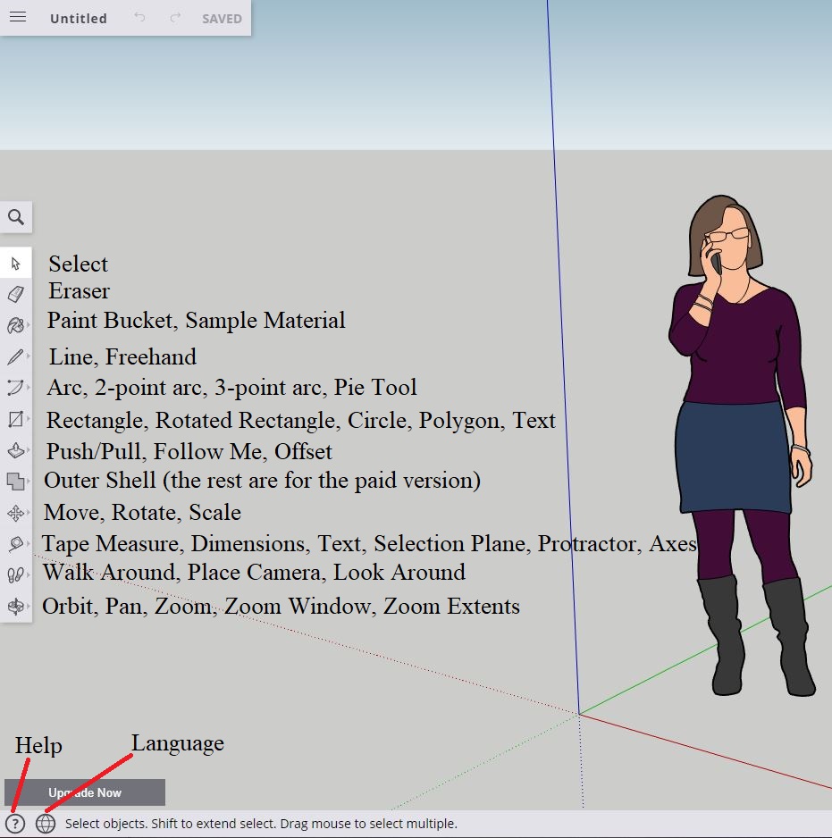
Now unfortunately the Outer shell menu has options we can’t access without the paid version. So you get the outer shell tool only, which basically does what it sounds like, combines two objects so you’re left with whatever the outside shell looks like. In essence it removes the intersecting faces so you’re left with one part. We never really covered the tool, or used it, but it’s useful if you want to combine simple shapes to make something more complex. You also have the help menu and language menu at the bottom of the screen (labeled above).
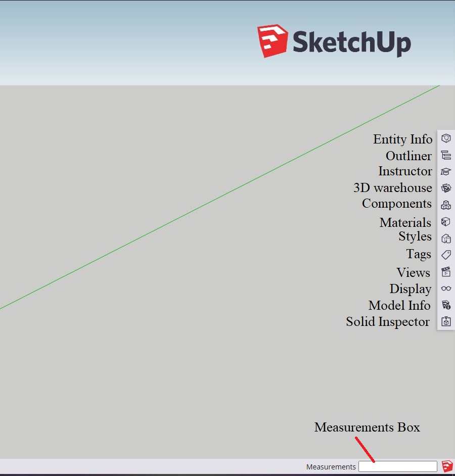
Now that we’ve covered the left side of the screen, let’s do a quick rundown of the right side. Most of this we covered in detail so this will just be a recap, but if I see something particularly confusing or something we haven’t really covered I’ll write a little note about it like I did above.
On the right side of the screen we have some tools we didn’t really get into. We covered the views menu in this post, along with a lot of the pop out menu options for the menu left and center on the screen (the one shown above). We also went into the materials menu in this post. Instructor is a helpful tool that gives you info about the tool you’ve selected. If you select the push/pull tool for example, it will explain how to use it.
Unfortunately, outliner is locked and that is equivalent to the feature tree in solidworks. It’s really useful, so it’s not surprising I guess that they locked it in the free version. Same with solid inspector, you need the paid version to use it and to make sure you have a solid body. By definition a solid body holds water, so it’s good to be able to check that.
We never covered the 3D warehouse, but it has a whole bunch of models that you can download and modify made by the community. Feel free to check it out, download some cool stuff and just have fun!
The styles menu lets you change the way the view looks. It’s not particularly useful for our purposes, so I didn’t really cover it. Feel free to poke around though and see if you like a different style! Tags are great if you have a large part and need to split things up a bit. You can name the tag whatever you want and in entity info you can set the tag for the part. For example, you could break the lamp we made into several different parts by using different tags to label them.
Lastly at the bottom we have our ever useful measurements box, we interacted with that guy a lot when we were modeling so you should be very familiar with how that works and how you can type in whatever dimension you want when you’re modeling.
Solidworks
Now solidworks has a much more dense menu and a lot of other features so instead of going through each one like I did here for sketchup, I’m going to cover some of the features and locations of things that would be good to know.
Our feature tree is where our part lives. It tells us the order of operations and how they were applied. The top of the feature tree is what was done first, and the bottom is what was done last. You can drag the order of operations around, but it will change the way the part is made so you may end up breaking the part. You cannot drag a operation past a previous operation if it depends on that operation. In short, if I cut a hole into a part and the hole is based on dimensions of that part or is drawn on the surface of that part I cannot put it before the creation of the part because the face I drew it on or the dimensions I related it to do not exist. Note my feature tree is empty because I haven’t created anything, but if you go back to our previous classes you’ll see how the feature tree is populated by whatever action you perform.
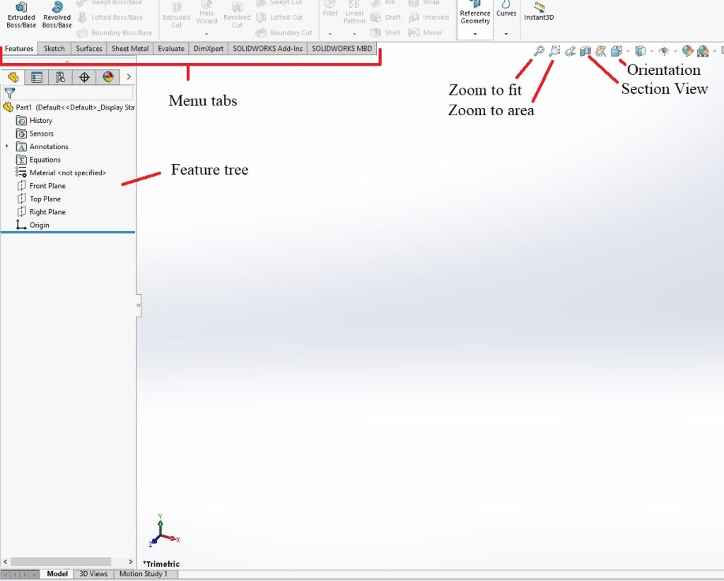
Above we have our menu tabs. Each tab is home to several different options. In this case I have the features tab shown. The first section (before the line drawn down the middle of the tab) are things that create material. I have my extruded boss/base tool, revolved boss/base tool, etc. On the other side of that line are my tools that remove material. Extruded cut, revolved cut, etc. All the cutting tools located in one group.
We have different tabs depending on where you are working. If you are in a sketch, chances are the tools you want will be in the sketch tab (unless you want to extrude/revolve/etc. the sketch).
We didn’t cover surfacing in my little online course, but I did in my in person class. Unlike all the things we covered, surfaces are not solid bodies. They have zero thickness, so they are quite literally just a surface. They give us the ability to create super complex shapes and things, so a very powerful tool, but they also can be hard to work with. Once you’ve created your part though, you can convert them (should you want to) into a solid body. So quite useful I think.
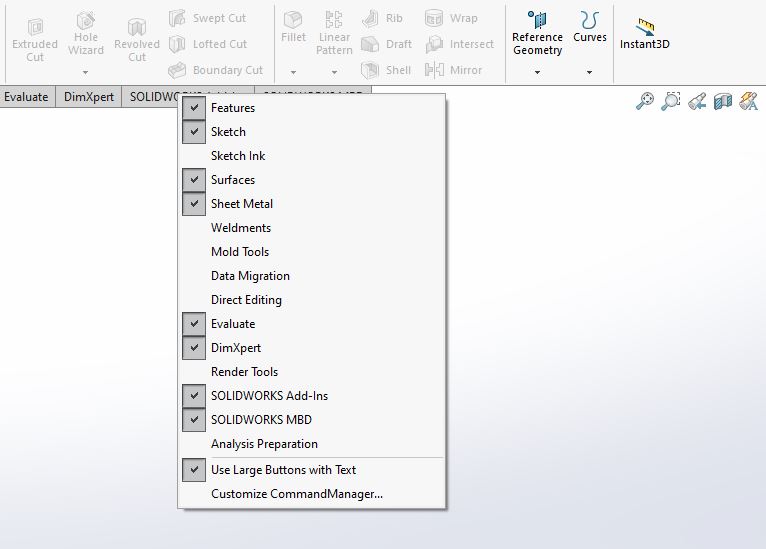
Now there are some hidden tabs that don’t get shown by default! If you right click the tabs you’ll see some options for tabs you don’t have visible. Such as the sheet metal tab (which I have turned on in the image above). Here’s the other options you have (below). Mold tools are for if you’re creating something that is going to be a model (for castings). Sheet metal should be obvious, but gives you tools to create parts using sheet metal operations (bends and the such).
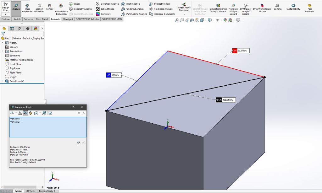
One thing we never covered, but can be useful is the evaluate tab (shown below). In particular the measure tool, which lets you click a face, line, or point, and get the distance between that and a second line,face, or point. It will return that information in x axis, y axis, z axis, and 3 dimensionally.
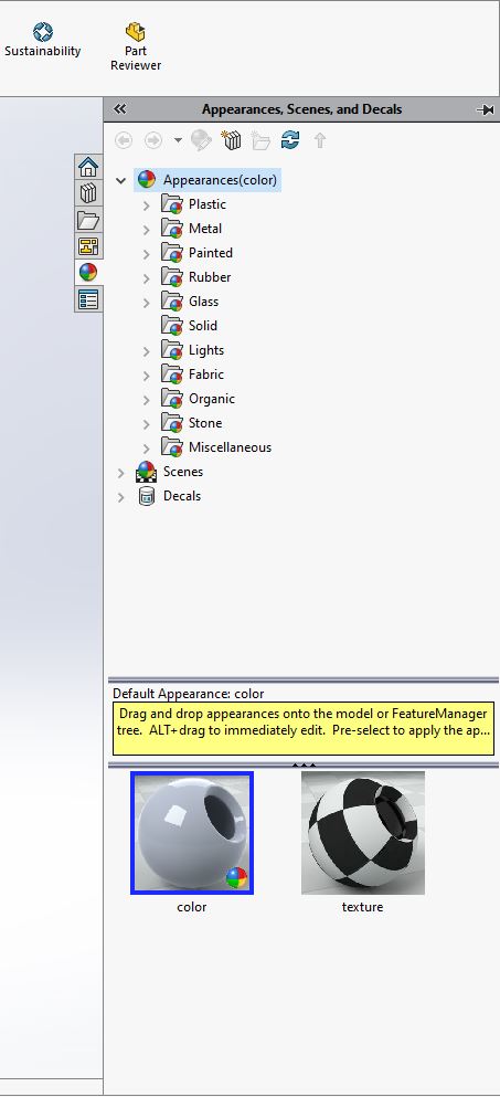
We already covered the appearance menu in depth, but here it is shown below. It’s located on the right side of the screen and the tab for it is a ball with a lot of different colors. Like sketchup it’s organized into folders, but unlike sketchup you get quite a selection.
Well everyone, this is it. I hate goodbyes, so let’s just say see you again next time? Maybe we can do another round of modeling next summer or something, who knows. I’ve had fun doing these little writeups, so maybe we can get more in depth next time and have some fun creating some really cool stuff. If you would like to see more of these, let me know, it might be the motivation I need to put together another round of solid modeling posts.
In any case, I sincerely hope that if you’ve followed along, you’ve learned enough to be proficient in modeling. Sometimes the first step is the most difficult, but once you get started things become easier to do. Trust me I wasn’t very good at solid modeling when I started and I cringe when I look back at some of my early attempts. I guess there’s just one thing left to say…
Until next time, don’t stop learning!


But enough about us, what about you?